Calibration method of camera and inertial sensor integrated positioning and attitude determining system

An inertial sensor and combined positioning technology, applied in the field of cameras, can solve problems such as low heading angle accuracy, achieve the effects of good robustness, practical calibration, and avoid system calibration errors

Inactive Publication Date: 2011-08-24
INST OF AUTOMATION CHINESE ACAD OF SCI
View PDF4 Cites 48 Cited by
  • Summary
  • Abstract
  • Description
  • Claims
  • Application Information

AI Technical Summary

Problems solved by technology

Since there are many parameters to be calibrated in this problem, and the accuracy of the heading angle in the three-axis direction angle (roll angle, pitch angle, and heading angle) output by the middle and low-end inertial sensors is l...

Method used


Image

  • Calibration method of camera and inertial sensor integrated positioning and attitude determining system
  • Calibration method of camera and inertial sensor integrated positioning and attitude determining system
  • Calibration method of camera and inertial sensor integrated positioning and attitude determining system

Examples


Embodiment Construction

[0025] Various details involved in the technical solution of the present invention will be described in detail below in conjunction with the accompanying drawings. It should be pointed out that the described embodiments are only intended to facilitate the understanding of the present invention, rather than limiting it in any way.

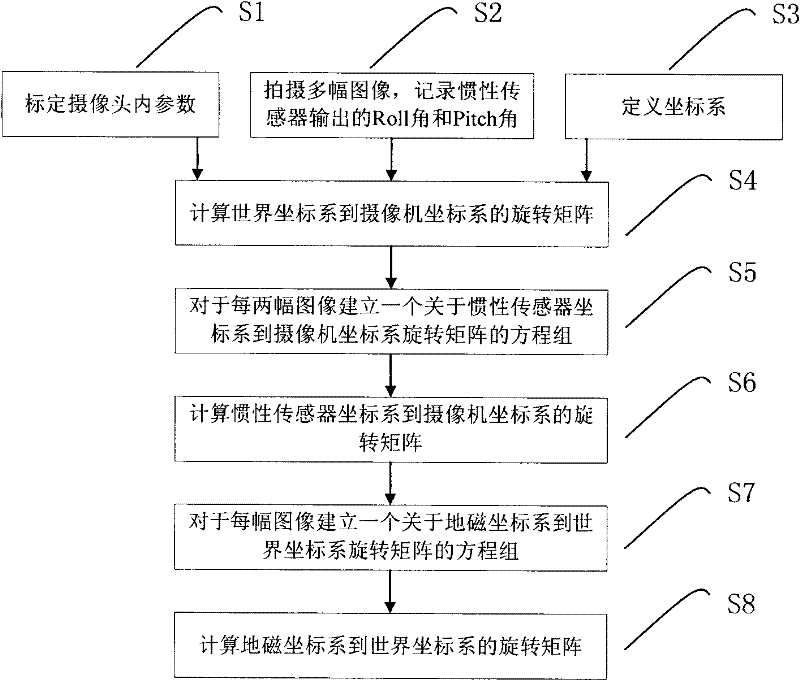
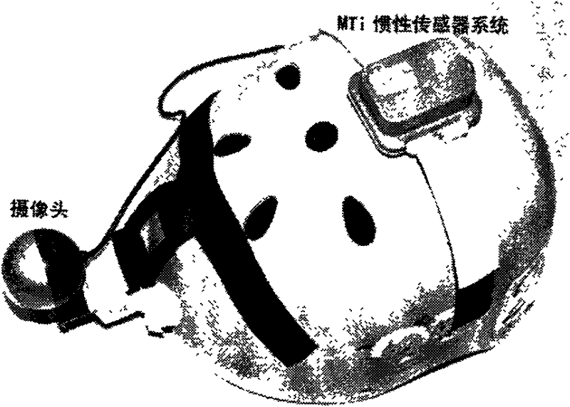
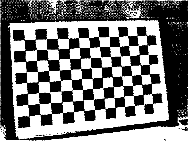
[0026] In order to realize the method of the present invention, adopt a computer of CPU2.33G, internal memory 2G during implementation, adopt VC to compile relevant program on computer, used camera is Logitech (logitech) C200, and inertial sensor is MTi miniature inertial sensor, calibration object is Black and white checkerboard. figure 1 Be the flowchart of the inventive method, figure 2 It is a hardware schematic diagram of the combined positioning and attitude determination system of the camera and the inertial sensor in the example of the present invention.

[0027] Concrete implementation steps of the present invention are as follows:

[0...


PUM


Abstract

The invention provides a calibration method of a camera and inertial sensor integrated positioning and attitude determining system. The method comprises the following steps: calibrating the intrinsic matrix of the camera; shooting a plurality of images of a calibration object with known dimensions from different angles, and recording the roll angle and the pitch angle output by the inertial sensor when each image is shot; defining a world coordinate system, a camera coordinate system, an inertial sensor coordinate system and a geomagnetic coordinate system; calculating the rotation matrix from the world coordinate system to the camera coordinate system at the moment based on the image information and spatial information of the calibration object in each image; integrating the shot images pairwise, establishing an equation set with respect to the rotation matrix from the inertial sensor coordinate system to the camera coordinate system for each group, and solving the equation set to calculate the rotation matrix from the inertial sensor coordinate system to the camera coordinate system; and establishing an equation set with respect to the rotation matrix from the geomagnetic coordinate system to the world coordinate system for each image, and solving the equation set to calculate the rotation matrix from the geomagnetic coordinate system to the world coordinate system.

Description

technical field [0001] The invention belongs to the technical field of cameras, and relates to a calibration technology for a combined positioning and attitude determination system of a camera and an inertial sensor. Background technique [0002] The combined positioning and attitude determination system of camera and inertial sensor is generally composed of a camera and an inertial sensor. Its function is to provide the position and attitude information of the camera synchronously. posture. This kind of system has a wide range of applications in the fields of robot autonomous navigation, virtual reality, augmented reality and so on. [0003] The combined positioning and attitude determination system of camera and inertial sensor involves four different coordinate systems: world coordinate system, camera coordinate system, geomagnetic coordinate system and inertial sensor coordinate system. The rotation transformation relationship between the world coordinate system and geo...

Claims


Application Information

Patent Timeline
IPC IPC(8): G01C25/00G06T7/00
Inventor 董秋雷顾照鹏胡占义
Owner INST OF AUTOMATION CHINESE ACAD OF SCI
Why Eureka
Try Eureka