Secondary mirror support structure of space optical remote sensor

A technology of space optical remote sensing and secondary mirror support, applied in optics, optical components, instruments, etc., can solve the problems of increasing the area blocked by the optical system, the fundamental frequency cannot meet the emission requirements, and the high imaging quality cannot be met, so as to improve Stiffness and stability, good optical system performance, effect of improving structural stiffness and thermal stability

Inactive Publication Date: 2011-08-24
BEIJING RES INST OF SPATIAL MECHANICAL & ELECTRICAL TECH
View PDF1 Cites 26 Cited by
  • Summary
  • Abstract
  • Description
  • Claims
  • Application Information

AI Technical Summary

Problems solved by technology

For RC optical systems with a diameter of more than 1 meter, if the supporting structure of the secondary mirror adopts the current typical veneer support method, such as figure 1 As shown, it is already difficult to meet the requirements of small obstruction, high rigidity, and light weight. Specifically, under the condition of small obstruction and light weight, the fundamental frequency cannot meet the emission requirements; in order to increase the fundamental frequency, it is usually used to increase the support rod perpendicular to the optical axis The cross-sectional area in the direction can significantly improve the axial stiffness of the support rod and increase the fundamental frequency. However, the increase in the cross-sectional area of ​​the support rod perpendicular to the optical axis will increase the weight and increase the area blocked by the optical system, resulting in a decrease in the MTF of the optical system. , leading to deterioration of imaging quality, unable to meet the requirements of high imaging quality
Therefore, the obstruction of the secondary mirror support rod is small, light weight and high rigidity are a pair of contradictions

Method used


Image

  • Secondary mirror support structure of space optical remote sensor
  • Secondary mirror support structure of space optical remote sensor
  • Secondary mirror support structure of space optical remote sensor

Examples


Embodiment Construction

[0015] Specific embodiments of the present invention will be further described in detail below in conjunction with the accompanying drawings.

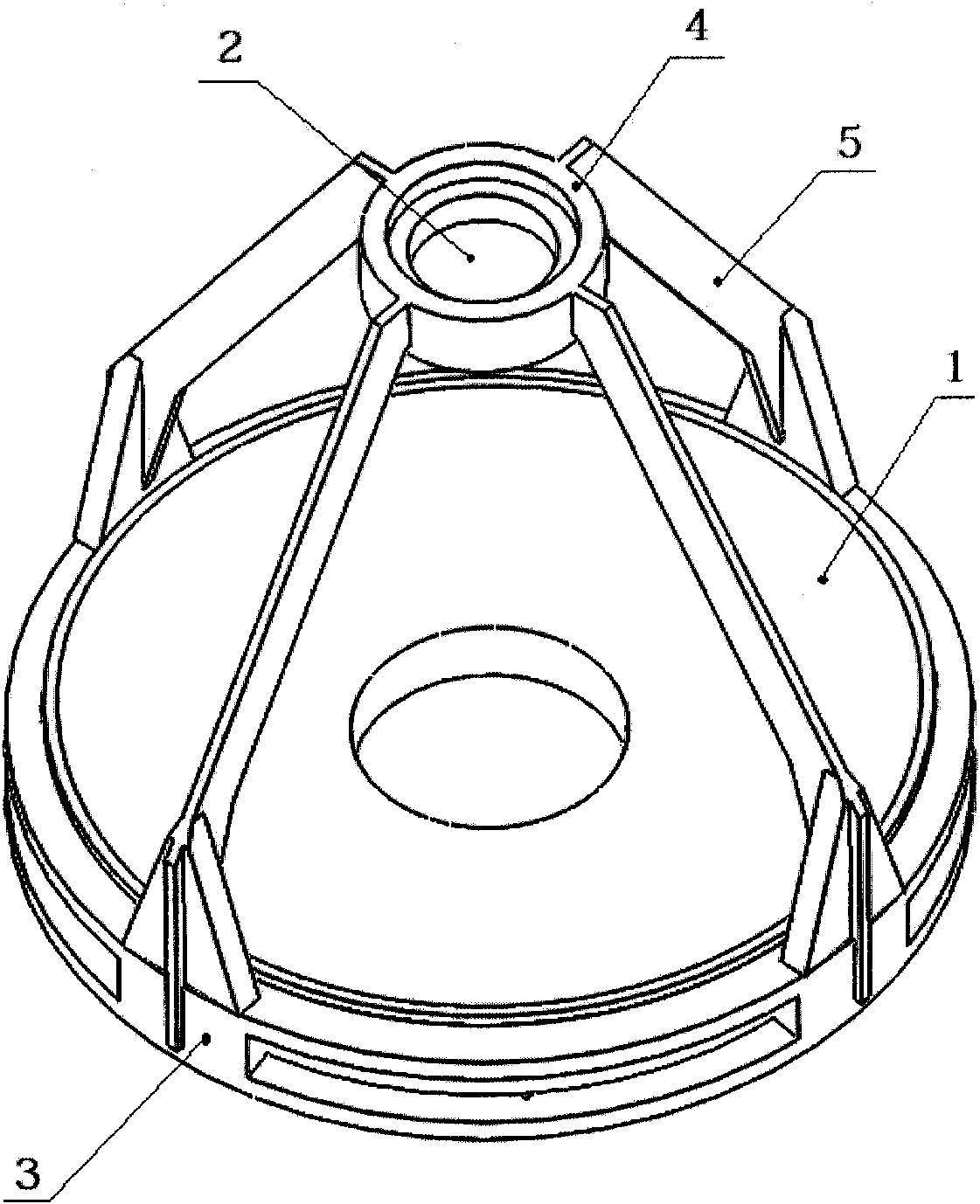
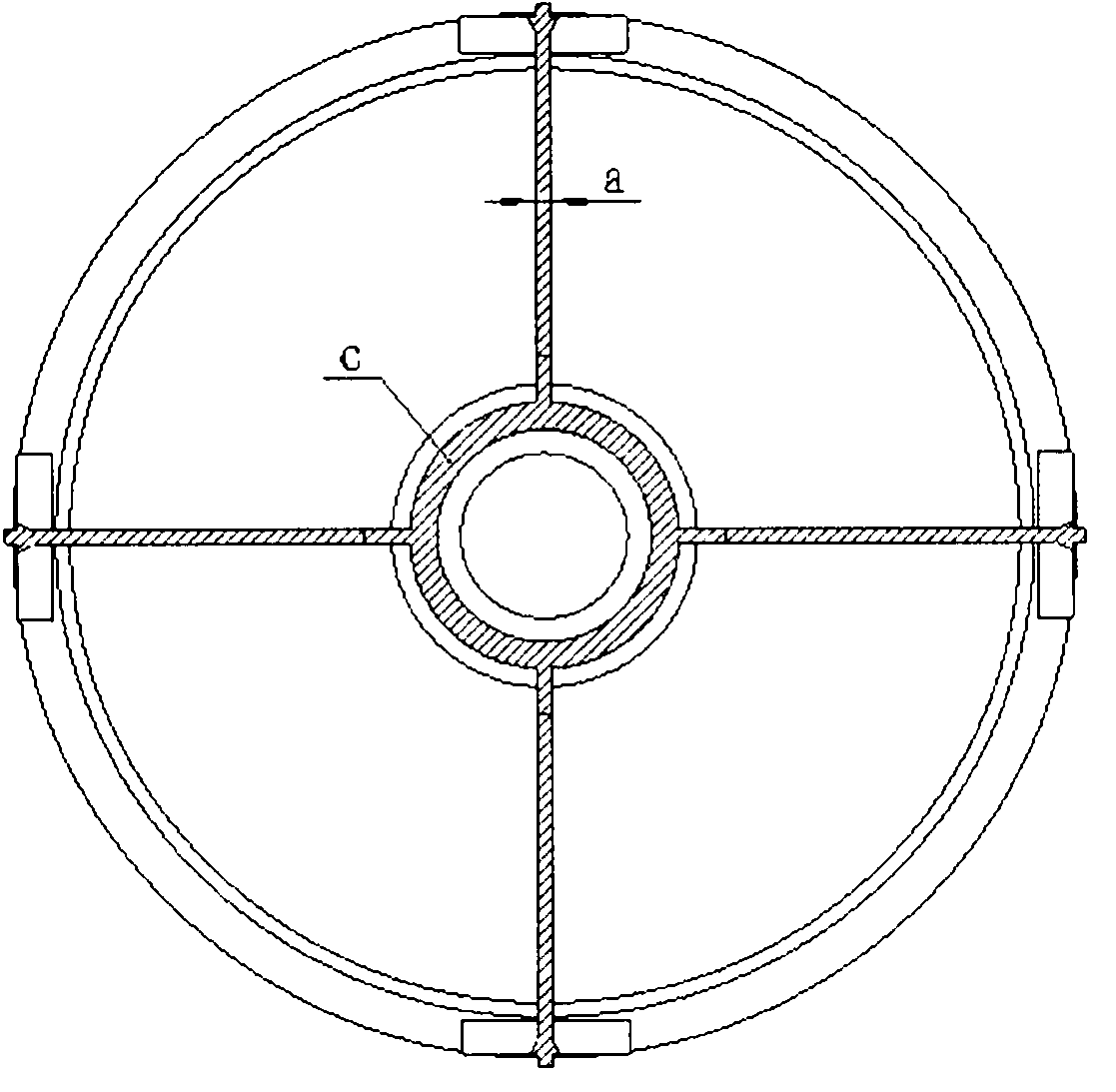
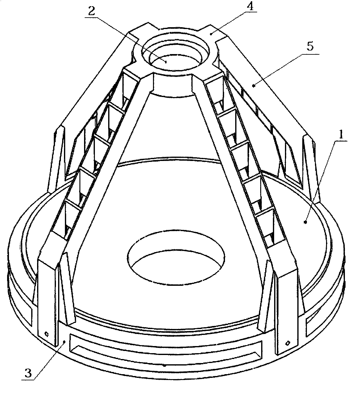
[0016] The invention provides a secondary mirror supporting structure of a space optical remote sensor, such as image 3 and Figure 4 As shown, it includes a primary mirror 1, a secondary mirror 2, a primary mirror frame 3, a secondary mirror frame 4 and four secondary mirror support rods 5; the secondary mirror frame 4 is connected to the primary mirror frame 3 through the secondary mirror support rods 5 and the secondary mirror frame 4 is parallel to Main mirror frame 3; Primary mirror 1 is fixedly installed on the main mirror frame 3, and secondary mirror 2 is fixedly installed on the secondary mirror frame 4, and primary mirror 1 is parallel to secondary mirror 2; The quantity of secondary mirror support rods 5 can be adjusted according to actual conditions, and can be Three, four, five and so on.

[0017] Each secondary mirror ...


PUM


Abstract

A secondary mirror support structure of a space optical remote sensor comprises a primary mirror, a secondary mirror, a primary mirror frame, a secondary mirror frame, and secondary mirror support bars, wherein the secondary mirror frame is connected with the primary mirror frame through the secondary mirror support bars, and is parallel to the primary mirror frame; the primary mirror is fixedly mounted on the primary mirror frame; the secondary mirror is fixedly mounted on the secondary mirror frame; the primary mirror is parallel to the secondary mirror; each secondary mirror support bar includes two single plates and a plurality of stiffening ribs; both ends of the single plate are respectively connected with the secondary mirror frame and the primary mirror frame; and the stiffening ribs are arranged between the two single plates of each secondary mirror support bar. The secondary mirror support structure resolves the contradiction of small obstruction ratio, light weight and high rigidity of the support bars. Under the condition of the same obstruction ratio and the same weight, the double-plate structure provided by the invention can greatly improve the rigidity and the thermal stability of the structure in comparison to the conventional single-plate structure; and the specific manifestations are that the fundamental frequency is improved by more than one time, the deformation displacement in the optical axis direction is reduced to about 10% that of the conventional single-plate structure, and the double-plate structure has lower vibration response and less thermal deformation.

Description

technical field [0001] The invention relates to a secondary mirror support structure of a space optical remote sensor, belonging to the technical field of space optical remote sensors. Background technique [0002] As the resolution requirements of my country's space optical remote sensors are getting higher and higher, the aperture of the optical system is also getting larger and larger, which puts forward higher and higher requirements for the stability of the supporting structure of the optical system. The role of the mirror support rod is becoming more and more important. On the one hand, the function of the secondary mirror support rod is to provide high rigidity support for the secondary mirror assembly to meet the satellite launch requirements, and on the other hand, to provide high stability for the secondary mirror assembly to ensure high imaging quality. For RC optical systems with a diameter of more than 1 meter, if the supporting structure of the secondary mirror...

Claims


Application Information

Patent Timeline
Patent Type & Authority Applications(China)
IPC IPC(8): G02B7/00G01S7/481G02B7/192
Inventor 林招荣谢冰
Owner BEIJING RES INST OF SPATIAL MECHANICAL & ELECTRICAL TECH
Why Eureka
Try Eureka