Mutual inductor device

A technology for transformers and mounting bases, which is applied to instruments, record carriers used by machines, and computer parts, etc., which can solve problems such as errors in warehousing and inbound and outbound systems, labor-intensive asset inventory, and difficult identification, etc., to reduce work Strength, avoid system errors, not easily damaged effect

Active Publication Date: 2011-08-24
STATE GRID CHONGQING ELECTRIC POWER CO ELECTRIC POWER RES INST
View PDF2 Cites 6 Cited by
  • Summary
  • Abstract
  • Description
  • Claims
  • Application Information

AI Technical Summary

Problems solved by technology

[0004] In view of this, the purpose of the present invention is to provide a transformer device, which can solve the current problems of difficult identification of transformers in the process of warehousing and asset management, system errors prone to occur in storage and out of storage, and labor-intensive asset inventory.

Method used


Image

  • Mutual inductor device
  • Mutual inductor device
  • Mutual inductor device

Examples


Embodiment Construction

[0020] In order to make the purpose, technical solutions and advantages of the embodiments of the present invention clearer, the technical solutions in the embodiments of the present invention will be clearly and completely described below in conjunction with the drawings in the embodiments of the present invention. Obviously, the described embodiments It is a part of embodiments of the present invention, but not all embodiments. Based on the embodiments of the present invention, all other embodiments obtained by persons of ordinary skill in the art without making creative efforts belong to the protection scope of the present invention.

[0021] The invention discloses a transformer device, which can solve the current problems of difficult identification of transformers in the process of storage and asset management, easy occurrence of system errors in storage and out of storage, and high labor intensity of asset inventory.

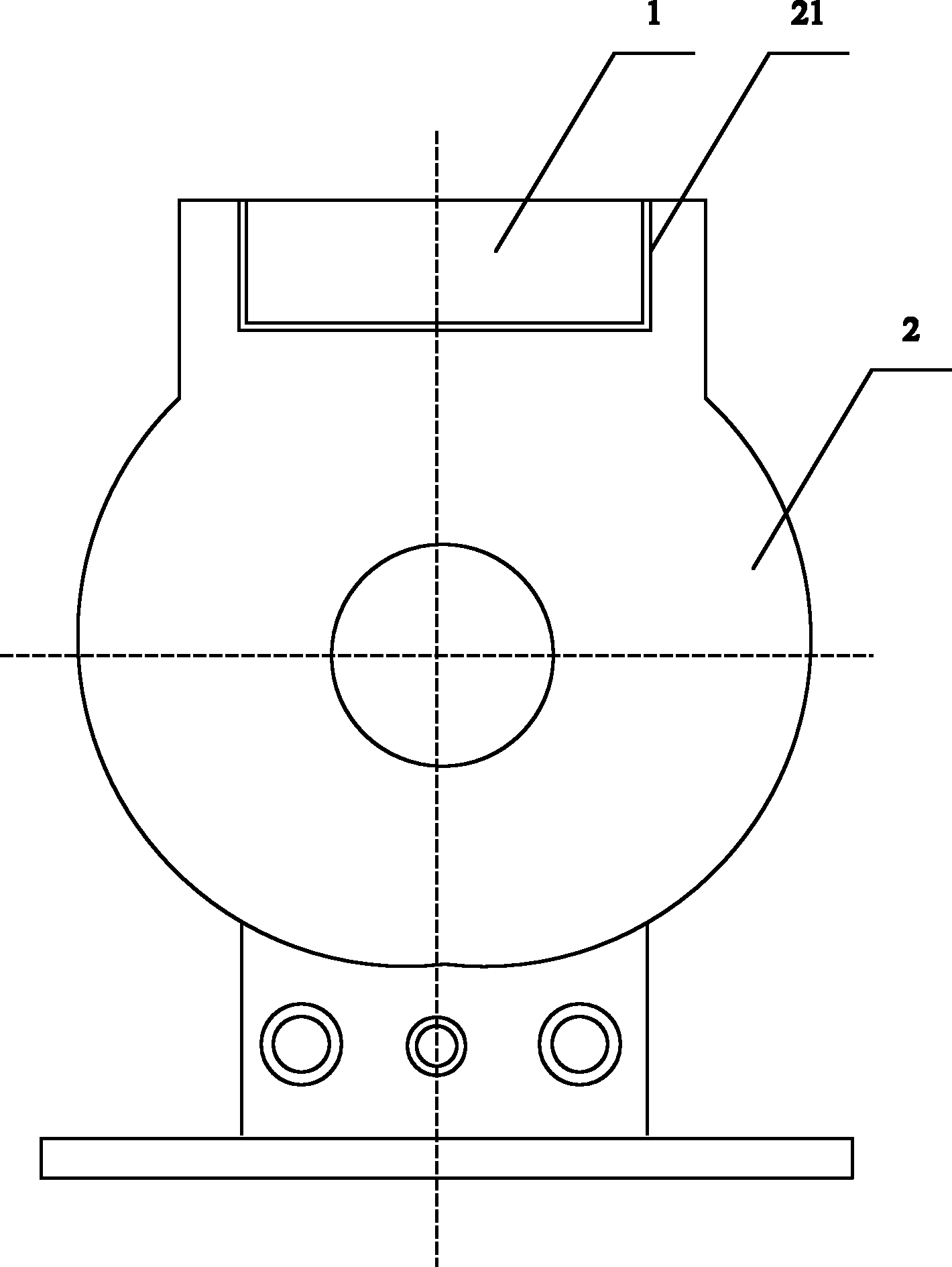
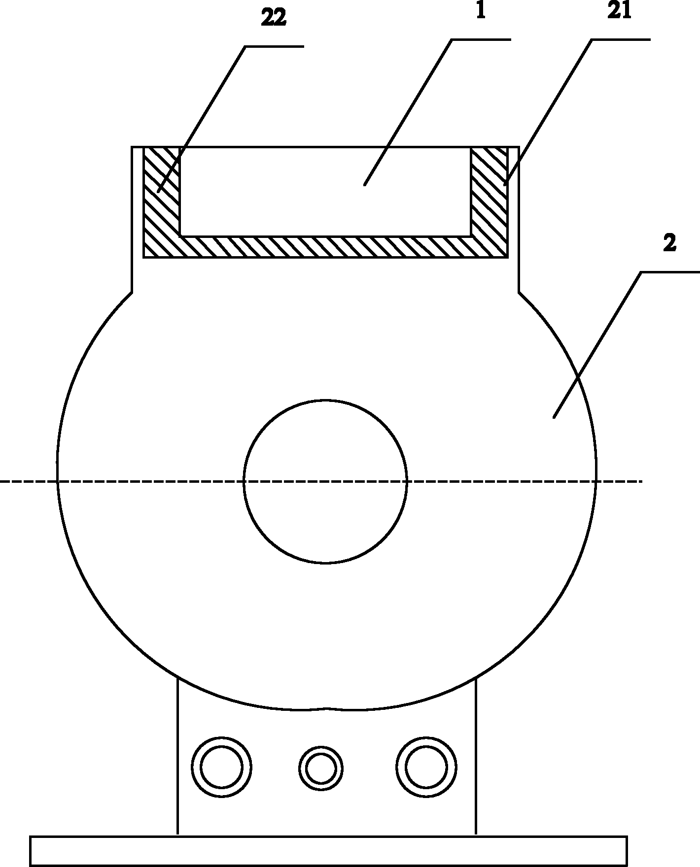
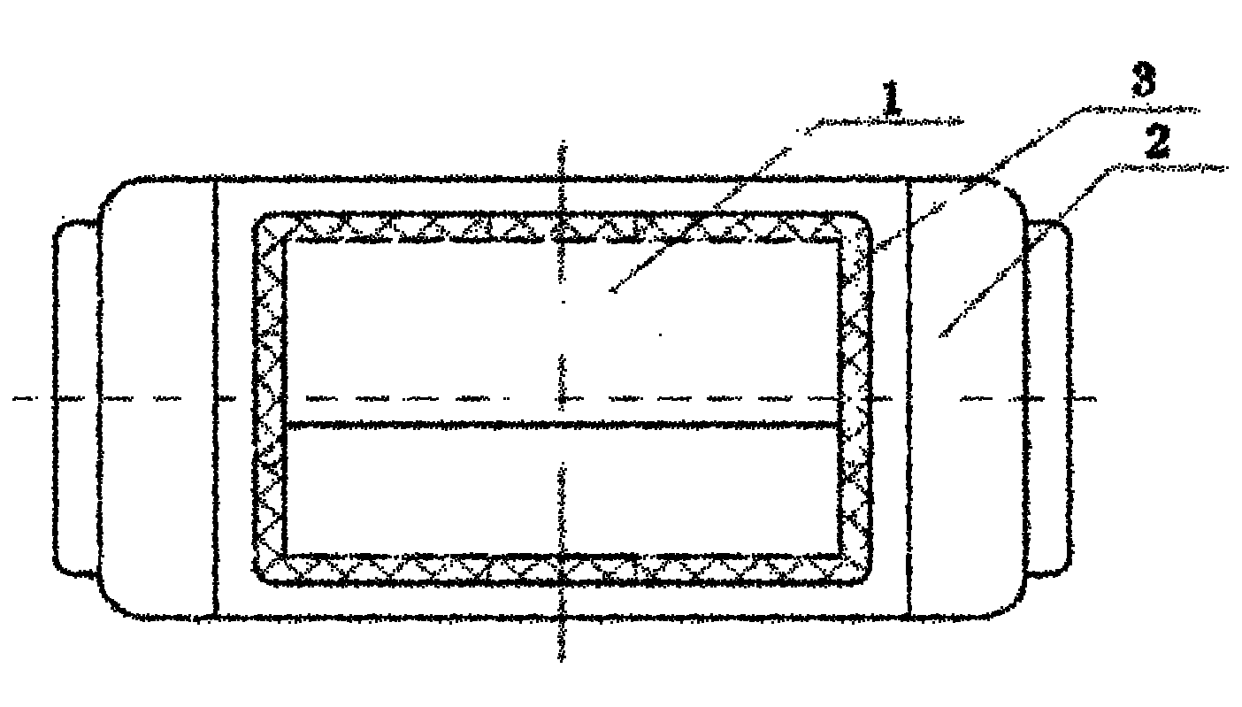
[0022] see figure 1 , figure 1 It is a side view ...


PUM


Abstract

The invention discloses a mutual inductor device. The device comprises a mutual inductor and an electronic label, wherein a slot is formed on the body of the mutual inductor; the electronic label is fixed in the slot; and the parameter information of the mutual inductor is stored in the electronic label. In the mutual inductor device, the electronic label is fixed with the mutual inductor to forma whole body, so that the electronic label cannot fall, is difficult to damage and cannot be replaced; the electronic label into which the parameter information of the mutual inductor is written has uniqueness, so that the identity of the mutual inductor can be effectively identified in the overall life cycle of the mutual inductor, and the execution of full-life quality management on products isfacilitated; the manual associated operation of the parameter information of the mutual inductor is not required, so that system faults due to manual operation errors in the process of delivering or warehousing stocks; and the electronic label has automatic scanning and quantity reading functions, so that the working intensity of workers can be reduced in the process of making an asset inventory.

Description

technical field [0001] The invention belongs to the technical field of electrical equipment, and in particular relates to a transformer device. Background technique [0002] At present, in the process of warehousing and asset management of transformers, power companies generally adopt the following method: manually paste a two-dimensional barcode on the transformer body, scan the barcode point-to-point with a scanning gun, and enter the information into the storage system. [0003] However, the above method has the following problems: the two-dimensional barcode manually pasted on the body of the transformer is easy to fall off, easily damaged, the scanning recognition rate is not high, and repeated identification is easy to occur, which makes it difficult to identify the transformer; all barcodes are associated manually. Operation, when there is a mistake in manual operation, a system error will occur in the storage and out of the warehouse; when the power supply enterprise...

Claims


Application Information

Patent Timeline
Patent Type & Authority Applications(China)
IPC IPC(8): G06K19/07
Inventor 冯凌周孔均郑可
Owner STATE GRID CHONGQING ELECTRIC POWER CO ELECTRIC POWER RES INST
Why Eureka
Try Eureka