Indirect evaporative cooler using membrane-contained, liquid desiccant for dehumidification

An evaporative cooler and liquid desiccant technology, applied in indirect heat exchangers, natural cooling systems, energy-saving heating/cooling, etc., can solve problems such as corrosion, expensive purchase, operation, and maintenance, and condensation

Active Publication Date: 2011-08-24
ALLIANCE FOR SUSTAINABLE ENERGY
View PDF9 Cites 52 Cited by
  • Summary
  • Abstract
  • Description
  • Claims
  • Application Information

AI Technical Summary

Problems solved by technology

Therefore, air conditioning systems may need to include refrigerated air conditioning to cool the air from the evaporative cooler, making such systems more expensive to purchase, operate, and maintain
[0006] Also, traditional evaporative coolers cannot dehumidify the air, and in fact often output air with 80% to 90% relative humidity, which is only acceptable in some very dry environments due to the very humid air Reduces evaporation rates for building occupants (e.g., reduces comfort levels) and may cause condensation, which can lead to corrosion or other problems
Dehumidification is provided as a second or subsequent stage in some evaporative coolers, for example by wicking a liquid desiccant into the walls of the air flow channels or chambers, but such systems are not widely available, This is due to increased operating and maintenance costs and considerations for desiccant exhaust with conditioned air

Method used


Image

  • Indirect evaporative cooler using membrane-contained, liquid desiccant for dehumidification
  • Indirect evaporative cooler using membrane-contained, liquid desiccant for dehumidification
  • Indirect evaporative cooler using membrane-contained, liquid desiccant for dehumidification

Examples


Embodiment Construction

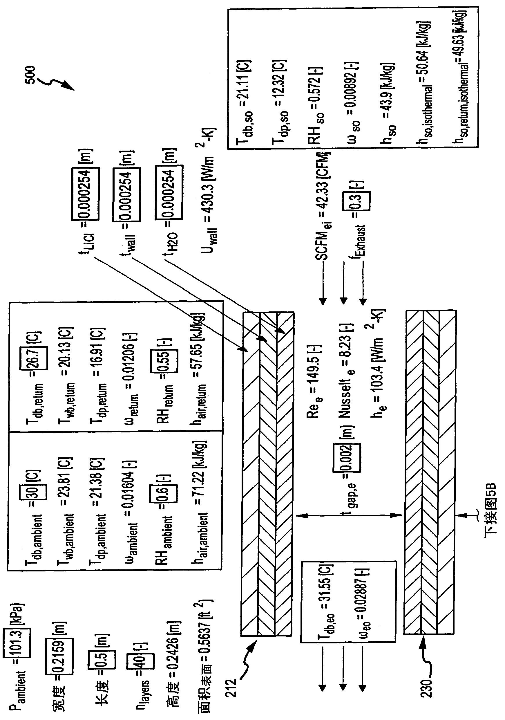
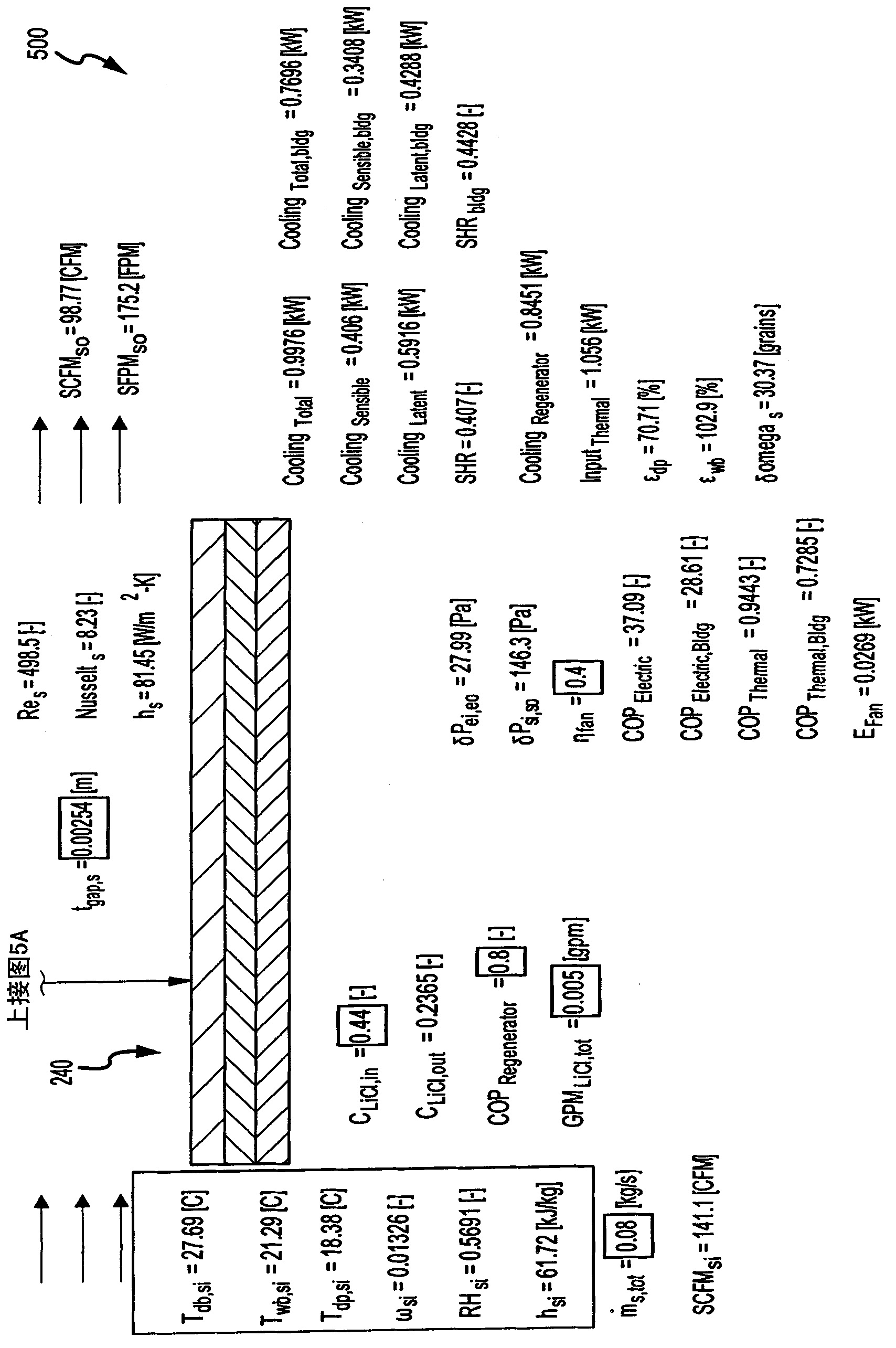
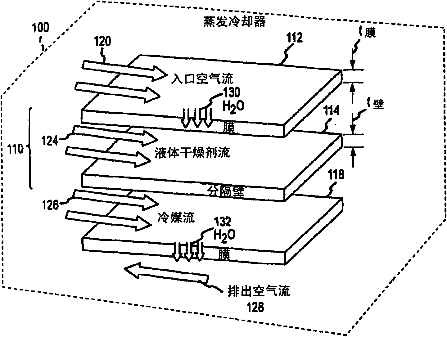
[0033] A description of an exemplary indirect evaporative cooler with dehumidification and mass / heat transfer components for a cooler that provides an inlet airflow chamber with an optional evaporative cooling system that encloses a liquid desiccant is provided next. The side wall defined by the permeable membrane. The assembly also includes an outlet or exhaust airflow chamber (eg, counter-flow to the inlet airflow) with side walls defined by a permeable membrane enclosing a refrigerant, such as water. In the embodiments described below, the membrane is "permeable" in the sense that moisture in the form of vapor (e.g., water in vapor state) can generally readily permeate, such as via evaporation, from the inlet supply air and liquid refrigerant through the membrane. However, the membrane generally traps or blocks the flow of moisture in liquid form, which instead is directed to flow within the channels or chambers. In some cases, liquid water is trapped within the membrane ...


PUM


Abstract

An indirect evaporative cooler for cooling inlet supply air from a first temperature to a second, lower temperature using a stream of liquid coolant and a stream of exhaust or purge air. The cooler includes a first flow channel for inlet supply air and a second flow channel adjacent the first for exhaust air. The first and second flow channels are defined in part by sheets of a membrane permeable to water vapor such that mass is transferred as a vapor through the membrane from the inlet supply air to a contained liquid desiccant for dehumidification and also to the exhaust air as heat is transferred from the inlet supply air to the liquid coolant. A separation wall divides the liquid desiccant and the coolant but allows heat to be transferred from the supply air to the coolant which releases water vapor to the counter or cross flowing exhaust air.

Description

[0001] contract source [0002] The US Government has rights in this invention under Contract No. DE-AC36-99GO10337 between the US Department of Energy and the National Renewable Energy Laboratory, a division of the Midwest Research Institute. Background technique [0003] Air conditioning is used all over the world to provide a comfortable and healthy indoor environment that is properly ventilated, cool and has adequate humidity control. While beneficial for conditioning the supplied air, conventional air conditioning systems are expensive to operate due to the large amount of energy used, such as electricity. As the demand for energy continues to grow, the cost of air conditioning is also expected to increase, and there is a growing demand for more efficient air conditioning methods and technologies. Also, increasing is the need for cooling technologies that do not use chemicals and materials such as many traditional refrigerants that could be environmentally damaging if re...

Claims


Application Information

Patent Timeline
Patent Type & Authority Applications(China)
IPC IPC(8): F24F5/00F28F1/32F28D7/00F24F1/0063
CPCF24F2001/0092Y02B30/545F24F2003/1435F28D21/0015F24F5/0035F24F3/1411F24F3/147F24F1/0007F24F3/1417Y02B30/54F24F1/0063F28D15/02F24F13/30F24F2003/1458
Inventor S·J·斯莱扎克E·J·科祖巴尔
Owner ALLIANCE FOR SUSTAINABLE ENERGY
Why Eureka
Try Eureka