
Magnetic-label sensor and cartridge

A magnetic label and sensor technology, applied in instruments, scientific instruments, measuring devices, etc., can solve the problems of reducing the sensor signal-to-noise ratio and detection limit, and achieve low detection limit, increase capacity, and improve signal-to-noise ratio. Effect

Inactive Publication Date: 2011-08-24
KONINK PHILIPS ELECTRONICS NV
View PDF3 Cites 3 Cited by
  • Summary
  • Abstract
  • Description
  • Claims
  • Application Information

AI Technical Summary

Problems solved by technology

This effect can limit the amount of particles that accumulate on the surface and thus the signal obtained from the (bio)sensor
This will disadvantageously reduce the signal-to-noise ratio of the sensor and the limit of detection (expressed as the minimum concentration of e.g. cardiac markers that can still be detected e.g. in blood)

Method used


Image

  • Magnetic-label sensor and cartridge
  • Magnetic-label sensor and cartridge
  • Magnetic-label sensor and cartridge

Examples


Embodiment Construction

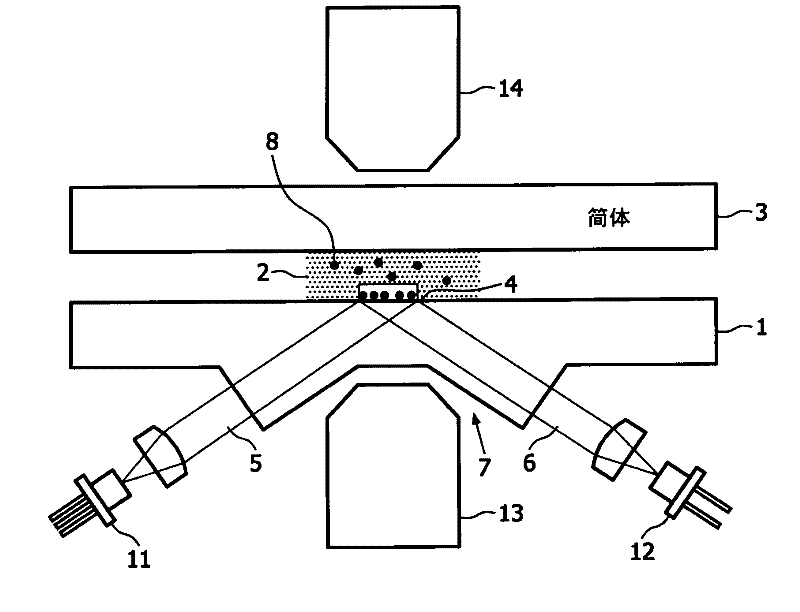
[0025] figure 1 Schematically showing the functional principle of the frustrated total internal reflection (FTIR) optical detection method. The illustrated cartridge comprises a base 1 and a cover part 3 with a fluid passage 2 therebetween. The fluid channel 2 is suitable for filling with a sample and is closed or covered by a cover part 3 . At the bottom, the fluid channel 2 is bounded by a sensor surface or sensor area 4, both terms are used below. Light ray 11 from a laser or LED enters the base 1 along a first optical path 5 , is reflected at said sensor surface 4 and leaves the base 1 along a second optical path 6 . The bottom 1 forms a recess 7 adapted to accommodate means 13 for providing a magnetic field.

[0026]Once the fluid channel 2 is filled or supplied with a fluid sample, the superparamagnetic label particles 8 supplied in dry form diffuse into the solution with the fluid sample. The terms "magnetic particle" and "magnetic label particle" are used equivalen...


PUM


Abstract

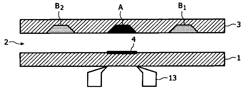
A cartridge (1,3) for a magnetic-label sensor, in particular for a magnetic-label biosensor, comprises a sensor area (4), a fluid channel (2) in contact with said sensor area and first (A) and second (Bl, B2) reservoirs in fluid communication with said fluid channel. The first reservoir comprises a first type of magnetic particles (8) and the second reservoir comprises a second type of magnetic particles (8a). The first type of magnetic particles are functionalized for binding with said sensor area, whereas the second type of magnetic particles are non- functionalized for binding with said sensor area. The magnetic particles (8, 8a) are manipulated using magnet (13). Detection is based on frustrated total internal reflection (FTIR) is hereby light from laser / LED (II) is reflected at sensor area (4) and detected by photodetector / CCD(12).

Description

technical field [0001] The invention relates to a magnetic label sensor, in particular to a magnetic label biological sensor and a cartridge used for the sensor. Background technique [0002] There is currently an increasing demand for biosensors. In general, biosensors can detect a given specific molecule within an analyte, where the number of said molecules is typically small. For example, the amount of drugs or cardiac markers in saliva or blood can be measured. Thus, target microparticles (eg, superparamagnetic label beads) are used to attach to specific attachment sites or only attachment points if the molecule to be detected is located within the analyte. One known technique to detect these label particles attached to the attachment point is frustrated total internal reflection (FTIR). At this point, light is coupled into the sample at an angle of total internal reflection. If there are no particles near the sample surface, the light is completely reflected. But i...

Claims


Application Information

Patent Timeline
Patent Type & Authority Applications(China)
IPC IPC(8): G01N33/543G01N35/00
CPCG01N2015/1493G01N15/1463G01N21/552G01N15/1433
Inventor H·范佐恩M·M·奥夫扬科J·H·尼乌文赫伊斯
Owner KONINK PHILIPS ELECTRONICS NV
Learn More