
Carbon fiber golf club shaft and formation method

A technology of golf clubs and molding methods, which is applied to golf balls, golf clubs, rackets, etc., and can solve problems such as poor hitting effect, poor bending resistance and torsion resistance of the shaft

Inactive Publication Date: 2011-08-31
叶金吉
View PDF5 Cites 9 Cited by
  • Summary
  • Abstract
  • Description
  • Claims
  • Application Information

AI Technical Summary

Problems solved by technology

Because the mandrel is a round rod, and the surface of the round rod is smooth and complete, the central hole of the carbon fiber golf club shaft is a round hole, and the thickness of the shaft is uniform and consistent. The bending resistance and torsion resistance are poor, and the hitting effect is also poor, which really needs further improvement

Method used


Image

  • Carbon fiber golf club shaft and formation method
  • Carbon fiber golf club shaft and formation method
  • Carbon fiber golf club shaft and formation method

Examples


Embodiment Construction

[0023] The present invention will be further described in detail below in conjunction with the accompanying drawings and specific embodiments.

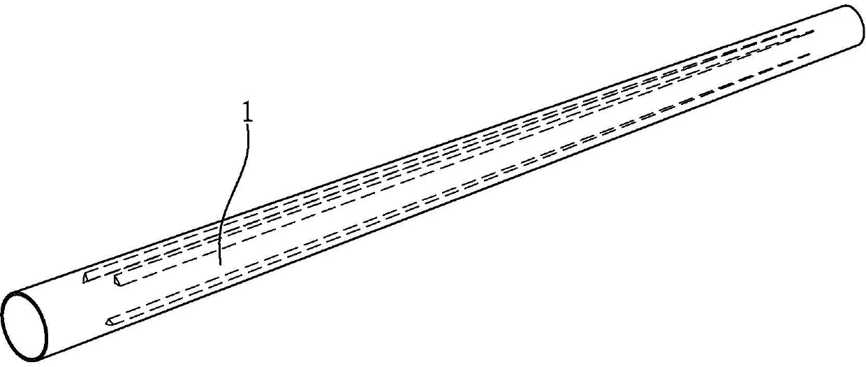
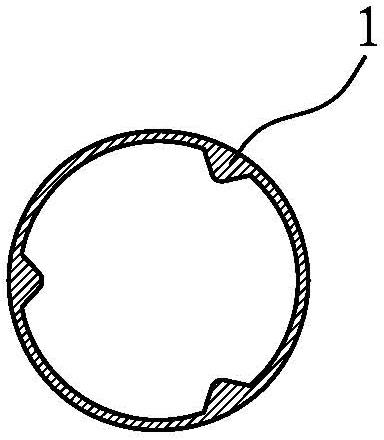
[0024] see figure 1 and figure 2 As shown, a carbon fiber golf club shaft disclosed by the present invention has a round hole in its center hole, and a convex line 1 is formed on the inner wall of the center hole. The number of raised lines 1 is not limited, preferably three to six, and this embodiment has three raised lines 1 . The convex strip 1 gradually becomes thinner from the big end to the small end of the club.

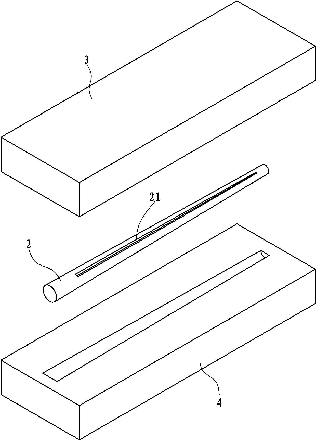
[0025] The molding method of the carbon fiber golf club shaft of the present invention is as follows, cooperate image 3 and Figure 4 Shown:

[0026] First select the circular core rod 2, the surface of the core rod 2 has a groove 21 for forming the convex strip 1; release agent and resin on the surface of the core rod;

[0027] Then, put the carbon fiber strip 5 in the groove 21 of the mandrel 2;

[0028] Th...


PUM


Abstract

The invention discloses a carbon fiber golf club shaft. A center hole of the carbon fiber golf club shaft is a circular hole, and a raised line is formed on the inner wall of the center hole. The invention also discloses a formation method of the carbon fiber golf club shaft, which comprises the following steps of: firstly, selecting a round mandrel, and applying a parting agent and resin are arranged on the surface of the mandrel, wherein the surface of the mandrel is provided with a groove for formation of the raised line; secondly, placing a carbon fiber strip in the groove of the mandrel; thirdly, coating a carbon fiber material on the mandrel, wrapping one layer of biaxially oriented polypropylene (BOPP) film on the carbon fiber material, and putting the mandrel in a mold cavity; fourthly, heating to 130 DEG C to cure carbon fiber; and finally, demolding, extracting the mandrel, removing the BOPP film, carrying out surface grinding, inspecting a blank product, and painting the blank product to manufacture the carbon fiber golf club shaft. In the invention, the raised line formed on the inner wall of the center hole of the club shaft plays the role of a reinforcing rib, so that the bending resistance and the torsion resistance of the club shaft are improved, and the batting effect is increased.

Description

technical field [0001] The invention relates to the technical field of golf clubs, in particular to a carbon fiber golf club shaft and a forming method thereof. Background technique [0002] A golf club is made up of a shaft, a head and a grip. In the prior art, the shaft is usually made of carbon fiber. Cover the mandrel with carbon fiber material, put it into the cavity of the mold, heat the carbon fiber to solidify, remove the mandrel after demoulding, and then make the carbon fiber golf club shaft. Because the mandrel is a round rod, and the surface of the round rod is smooth and complete, the central hole of the carbon fiber golf club shaft is a round hole, and the thickness of the shaft is uniform and consistent. The bending resistance and torsion resistance are poor, and the batting effect is also poor, which really needs further improvement. Contents of the invention [0003] The object of the present invention is to provide a carbon fiber golf club shaft and it...

Claims


Application Information

Patent Timeline
Patent Type & Authority Applications(China)
IPC IPC(8): A63B53/10A63B102/32
Inventor 叶金吉
Owner 叶金吉
Learn More