Aerated concrete block masonry composite wall reinforced with embedded reinforcements and borehole core columns

A kind of aerated concrete, embedded technology, applied in the direction of wall, building material processing, building components, etc., to achieve good promotion and application prospects, to achieve the effect of wall insulation and load-bearing integration

Inactive Publication Date: 2011-08-31
BEIJING UNIV OF TECH
View PDF6 Cites 9 Cited by
  • Summary
  • Abstract
  • Description
  • Claims
  • Application Information

AI Technical Summary

Problems solved by technology

However, the masonry walls of aerated concrete blocks in earthquake areas should generally be built with special mortar, and the thickness of the

Method used


Image

  • Aerated concrete block masonry composite wall reinforced with embedded reinforcements and borehole core columns
  • Aerated concrete block masonry composite wall reinforced with embedded reinforcements and borehole core columns
  • Aerated concrete block masonry composite wall reinforced with embedded reinforcements and borehole core columns

Examples


Embodiment 1

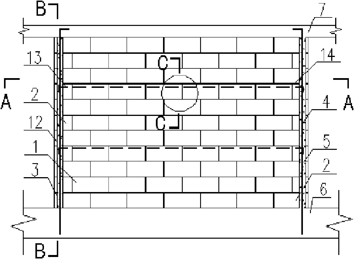
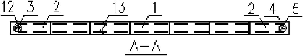
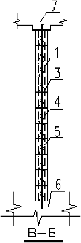
[0031] Figure 1 ~ Figure 4 It is a wall without openings, and its main part 1 is made of aerated concrete blocks and mortar. Before masonry, all the outermost blocks 2 on the left and right sides of the wall are drilled into cylindrical holes 3. The holes of the block penetrate up and down, and there are long longitudinal steel bars 4 inside. The steel bars extend from the reinforced concrete cast-in-place beam slab (or foundation) 6 at the lower end of the wall of the floor and extend into the reinforced concrete cast-in-place beam at the upper end of the wall Inside the plate 7, the upper and lower ends are reliably anchored. In the construction, when the wall is built to the place where the built-in reinforcement is to be installed, the upper surface of the block is drilled through the long groove 11 along the length of the wall, and the horizontal steel bar 13 is placed inside, and the steel bar The two ends extend into the holes provided for the pouring core column 12 at ...

Embodiment 2

[0033] Figure 5 ~ Figure 8 It is a wall with a door opening. The main part 1 of the wall is made of aerated concrete blocks and mortar. The door opening separates the wall into left and right wall limbs. Core columns 12 are provided at both ends of the wall and both sides of the door opening. Before masonry, drill cylindrical holes 3 on all the outermost blocks 2 on the left and right sides of the wall, the blocks 9 on both sides of the door opening and the corresponding positions of the two ends of the door lintel 8 and the corresponding positions of the blocks 10 above. When masonry, the hole of the block is penetrated up and down, and there are long longitudinal steel bars 4 inside. The steel bars extend from the reinforced concrete cast-in-place beam slab (or foundation) 6 at the lower end of the wall of the floor and extend into the upper end of the wall. Inside the cast-in-place concrete beam slab 7, the upper and lower ends are reliably anchored. The left and right lim...


PUM


Abstract

The invention discloses an aerated concrete block masonry composite wall reinforced with embedded reinforcements and borehole core columns, which belongs to the field of masonry structure and is mainly applied to the building structure engineering. The aerated concrete block masonry composite wall comprises block masonry composed of aerated concrete blocks and dedicated mortar, wall core columns vertically arranged in the block masonry and embedded reinforcements horizontally arranged in the block masonry; horizontal steel bars are generally arranged in block hollow grooves arranged along the length direction of a wall body, and the horizontal steel bars and mortar filled in horizontal mortar joints during the wall building form the embedded reinforcements; vertically through holes are drilled on the block masonry, and core column steel bars are vertically arranged in the holes; and the core column steel bars and core column concrete made of concrete poured after the wall building form wall core columns. The aerated concrete block masonry composite wall disclosed by the invention has relatively good popularization and application prospect in the load-bearing walls of multi-layer masonry structures in seismic areas and even non-load-bearing walls taking aerated concrete block masonries as filler walls in various structure systems.

Description

Technical field: [0001] The present invention is an aerated concrete block masonry composite wall reinforced with built-in reinforcement and drilled core columns, which belongs to the field of masonry structure and is mainly used for building structural engineering, especially, but not limited to, those with a small number of layers Village houses. Background technique: [0002] Aerated concrete block masonry walls are currently mainly used in construction for non-load-bearing purposes such as infill walls. As clay bricks are gradually banned, there is an urgent need for new materials to replace them to build multi-layer masonry buildings. Start to study its use as a load-bearing wall of masonry structure. However, the strength of this material itself is not high, and the integrity of the masonry wall is poor. Under the action of a strong earthquake, the wall is prone to lose its bearing capacity soon after cracking, resulting in collapse. Therefore, improving the seismic perfo...

Claims


Application Information

Patent Timeline
IPC IPC(8): E04B2/64E04B2/68E04G21/00
Inventor 赵均凌沛春朱玉玉陈丽颖曾明许洋
Owner BEIJING UNIV OF TECH
Why Eureka
Try Eureka