System for monitoring wear of pantograph sliding plate

A pantograph sliding plate and monitoring system technology, applied in measuring devices, instruments, optical devices, etc., can solve problems such as low efficiency, poor accuracy, and easy misjudgment, achieve high efficiency and accuracy, and avoid pantograph-catenary accidents. , the effect of not easily misjudged

Inactive Publication Date: 2011-08-31
DONGGUAN NANNAR ELECTRONICS TECH
View PDF4 Cites 15 Cited by
  • Summary
  • Abstract
  • Description
  • Claims
  • Application Information

AI Technical Summary

Problems solved by technology

[0003] At present, the detection method of pantograph wear is relatively primitive, mainly through manual visual inspection every day when locomotives leave and

Method used


Image

  • System for monitoring wear of pantograph sliding plate
  • System for monitoring wear of pantograph sliding plate
  • System for monitoring wear of pantograph sliding plate

Examples


Embodiment Construction

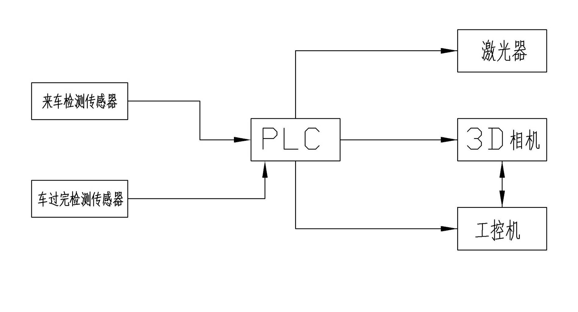
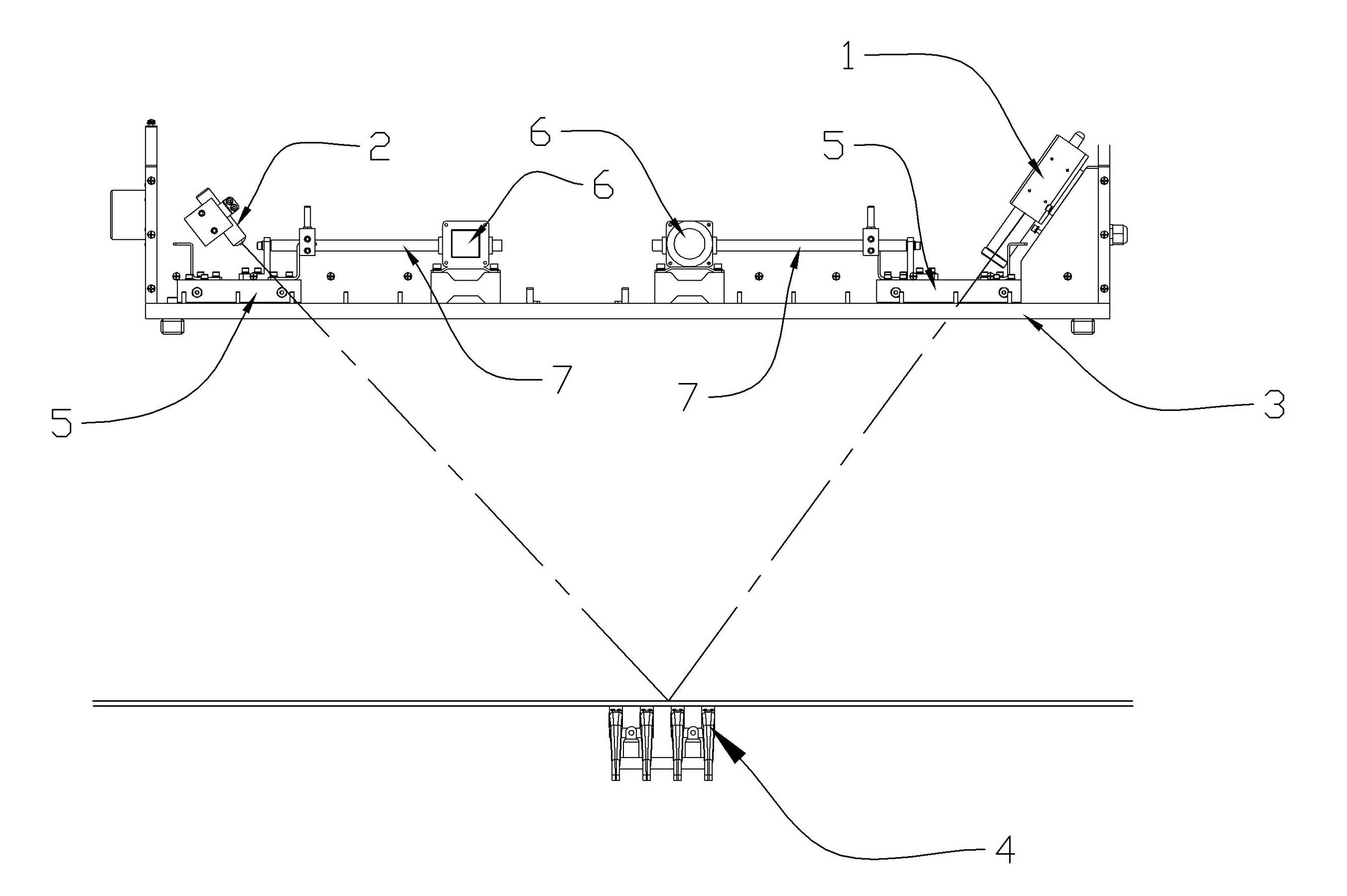
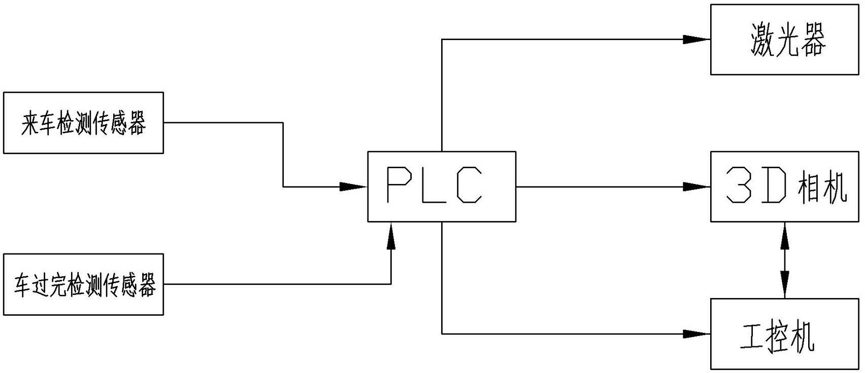
[0010] like figure 1 , one A pantograph slide wear monitoring system, including a three-dimensional stereo camera 1 (3D camera) and a laser 2; the 3D camera and the laser are installed above the monitoring place, which can be installed above the monitoring place through a fixed frame 3, relative to the fixed frame It can be rotated, and the angle can be adjusted by rotating after installation, so that when the pantograph 4 passes by, the laser can fully and clearly illuminate the pantograph, and the 3D camera can fully and clearly photograph the pantograph. For example, adjust the laser so that the irradiating light can fully and clearly cover the pantograph passing through the bottom, and the 3D camera can be set symmetrically with it, and the incident light of the laser is reflected by the pantograph slide and just irradiates the lens direction of the 3D camera. The 3D camera and laser are connected to the PLC controller, and the PLC controller controls the switch of its p...


PUM


Abstract

The invention discloses a system for monitoring wear of a pantograph sliding plate. The system comprises a three-dimensional (3D) camera and a laser, wherein the three-dimensional camera and the laser are connected with a PLC (Programmable logic controller), and are controlled to be switched on and off by the PLC; the PLC is also connected with an industrial control computer; and the industrial control computer is connected with the 3D camera through a broadband network, and can be used for receiving and storing photos transmitted by the 3D camera through the broadband network. During the passage of a pantograph, the 3D camera can be used for transmitting shot photos of the top of the pantograph through the broadband network, the industrial controllable computer is used for analyzing 3D photos, and the 3D coordinate values of the sliding plate on the top of the pantograph can be obtained clearly, so that the wear condition of the sliding plate can be obtained clearly and accurately, monitoring of the wear condition of the pantograph sliding plate can be automatically realized, and high efficiency and high accuracy are achieved.

Description

technical field [0001] The invention relates to a system for monitoring the wearing condition of pantographs used in rail trains, locomotives, trams and the like. Background technique [0002] A pantograph is an electrical device installed on the top of an electric traction locomotive to obtain electrical energy from the catenary. It usually consists of the top slide plate, upper frame, lower frame, bottom frame, bow spring, transmission cylinder, supporting insulator and other components. In order to ensure the smooth circulation of the pantograph traction current, the sliding plate on the top of the pantograph and the contact line of the catenary must be in reliable contact with a certain contact pressure. However, the pantograph travels at high speed with the locomotive, and the contact wire always slides relative to the sliding plate on the top of the pantograph during the running of the locomotive. During the relative sliding process between the contact wire and the sl...

Claims


Application Information

Patent Timeline
IPC IPC(8): G01B11/00
Inventor 朱晓东
Owner DONGGUAN NANNAR ELECTRONICS TECH
Why Eureka
Try Eureka