Loading method for concrete member flexural test

A concrete and component technology, applied in the direction of applying a stable bending force to test the strength of materials, can solve the problems of increased test workload and difficult to continue to use, and achieve the effect of small slippage, simple structure and reliable force

Inactive Publication Date: 2011-08-31
YANGZHOU UNIV
View PDF5 Cites 16 Cited by
  • Summary
  • Abstract
  • Description
  • Claims
  • Application Information

AI Technical Summary

Problems solved by technology

Such a test method needs to pour a batch of distribution beams matching the size of the component...

Method used


Image

  • Loading method for concrete member flexural test
  • Loading method for concrete member flexural test
  • Loading method for concrete member flexural test

Examples


Embodiment 1

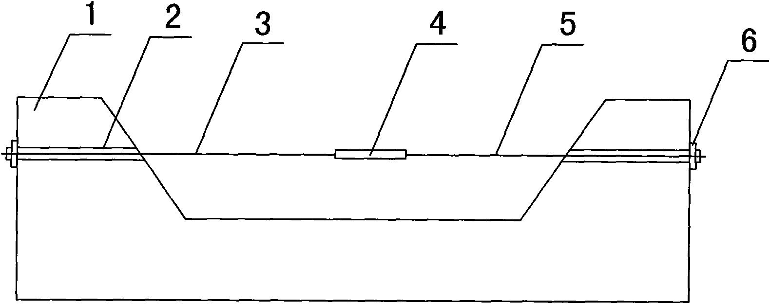
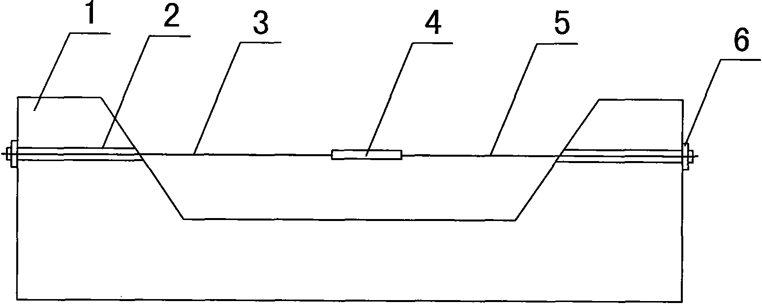
[0025] Such as figure 1 As shown, pouring plain concrete (or reinforced concrete) component 3, the concrete component is 800mm long, 100mm wide, and 100mm high. Corbels 1 are set at both ends of the concrete member. The height of the corbel is 150mm, the length of the bottom of the corbel is 200mm, and the length of the upper end of the corbel is 100mm. The corbel and the concrete member are poured into one body at the same time. Leave the circular tunnel 2 (the tunnel diameter is 30mm, it is advisable to pass through the screw end rod), the holes of the two circular tunnels are on the same axis, and the steel plate with holes is embedded in the tunnel outside. After pouring, the concrete components were cured for 28 days according to the existing concrete curing conditions and methods (according to the current national standard "Test Method for Mechanical Properties of Ordinary Concrete"), the strength of the concrete was measured, and the cracking load of the concrete compon...

Embodiment 2

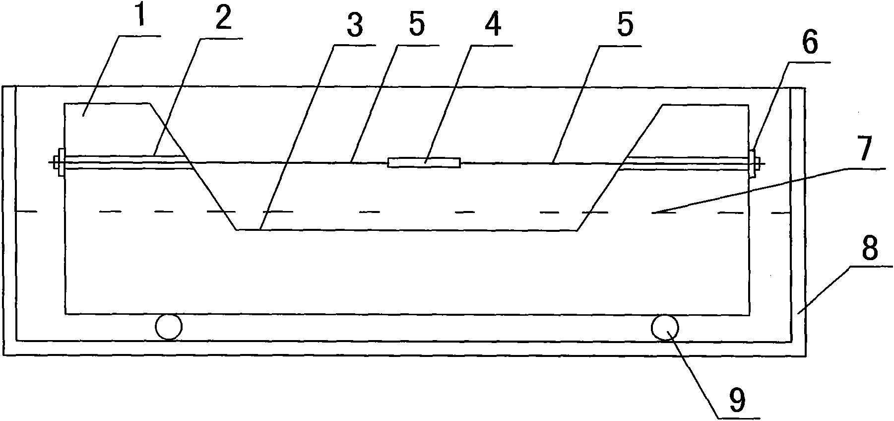
[0027] Such as figure 2 as shown in figure 1 As shown, pouring plain concrete (or reinforced concrete) component 3, the concrete component is 800mm long, 100mm wide, and 100mm high. Corbels 1 are set at both ends of the concrete member. The height of the corbel is 150mm, the length of the bottom of the corbel is 200mm, and the length of the upper end of the corbel is 100mm. The corbel and the concrete member are poured into one body at the same time. Leave the circular tunnel 2 (the tunnel diameter is 30mm, it is advisable to pass through the screw end rod), the holes of the two circular tunnels are on the same axis, and the steel plate with holes is embedded in the tunnel outside. After pouring, the concrete components were cured for 28 days according to the existing concrete curing conditions and methods (according to the current national standard "Test Method for Mechanical Properties of Ordinary Concrete"), the strength of the concrete was measured, and the cracking load...


PUM


Abstract

The invention relates to a loading method for a concrete member flexural test, which comprises the following steps: (1) pouring a concrete member and arranging brackets and hole channels at two ends of the concrete member; (2) maintaining the poured concrete member for 28 days, testing the strength and setting the size of load; (3) enabling two screw rods both having two threaded ends to penetrate through the reserved round hole channels in the brackets, connecting the screw rods by using a reinforcement stress meter in the middle, and screwing screw nuts on the two ends; (4) connecting the reinforcement stress meter with an XP02 type vibration wire frequency meter, measuring an initial frequency value f0 of the reinforcement stress meter, and calculating a vibration wire frequency fn corresponding to a tensile stress delta designed for the test; and (5) using a wrench to tighten the screw nuts for applying load till the value on the XP02 type vibration wire frequency meter reaches the vibration wire frequency fn. According to the method, the loading force is reliable, the device is simple, the operation is convenient, the slipping volume is small, the load value is stable, and the method is suitable for the concrete member flexural long-term loading test, especially the loading test in a soaking condition.

Description

technical field [0001] The invention relates to a test loading method for applying bending moment to a concrete component. The test loading device is a self-balancing device, which is especially suitable for the long-term load test of the concrete bending component and the loading test of the concrete component under soaking conditions. Background technique [0002] In the test to study the mechanical properties of concrete members under the action of bending moment (or eccentric load), it is required to generate tensile stress and compressive stress in the normal section of the member, and the commonly used loading methods include heavy object loading method, hydraulic loading method or mechanical tools loading method. The heavy object loading method is to use the weight of the loaded object itself as the test load to directly apply to the component to generate a bending moment on the front section; the hydraulic loading method is to use the hydraulic loader to realize two-...

Claims


Application Information

Patent Timeline
IPC IPC(8): G01N3/20
Inventor 李琮琦骆静静杨鼎宜
Owner YANGZHOU UNIV
Why Eureka
Try Eureka