Arrangement method and structure of bridge electrode

An electrode structure, bridge-connected technology, applied in the direction of electrical digital data processing, data processing input/output process, instruments, etc., can solve problems such as poor appearance, poor electrical properties, inability to conduct, etc. Effect

Inactive Publication Date: 2011-08-31
范莉立
View PDF3 Cites 12 Cited by
  • Summary
  • Abstract
  • Description
  • Claims
  • Application Information

AI Technical Summary

Problems solved by technology

[0003] However, the metal wires traditionally arranged on the insulating layer may be damaged in the subsequent manufacturing process, making it impossible to conduct, and then resulting in a decline in the production yield of the capacitive touch panel.
[0004] In addition, in general factories, in terms of photomask design, the pattern line width of the production photomask is the same as the pattern line

Method used


Image

  • Arrangement method and structure of bridge electrode
  • Arrangement method and structure of bridge electrode
  • Arrangement method and structure of bridge electrode

Examples


Embodiment Construction

[0030] In order to fully understand the purpose, characteristics and effects of the present invention, the present invention will be described in detail through the following specific embodiments, and in conjunction with the attached drawings, as follows:

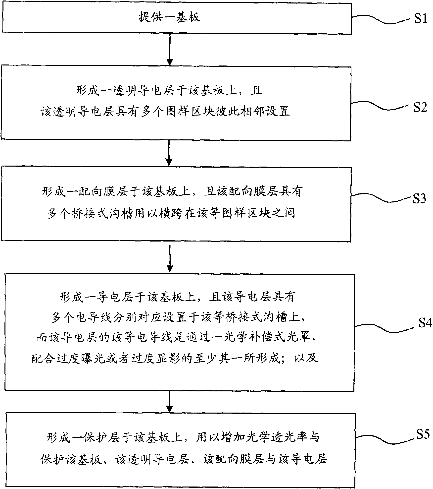
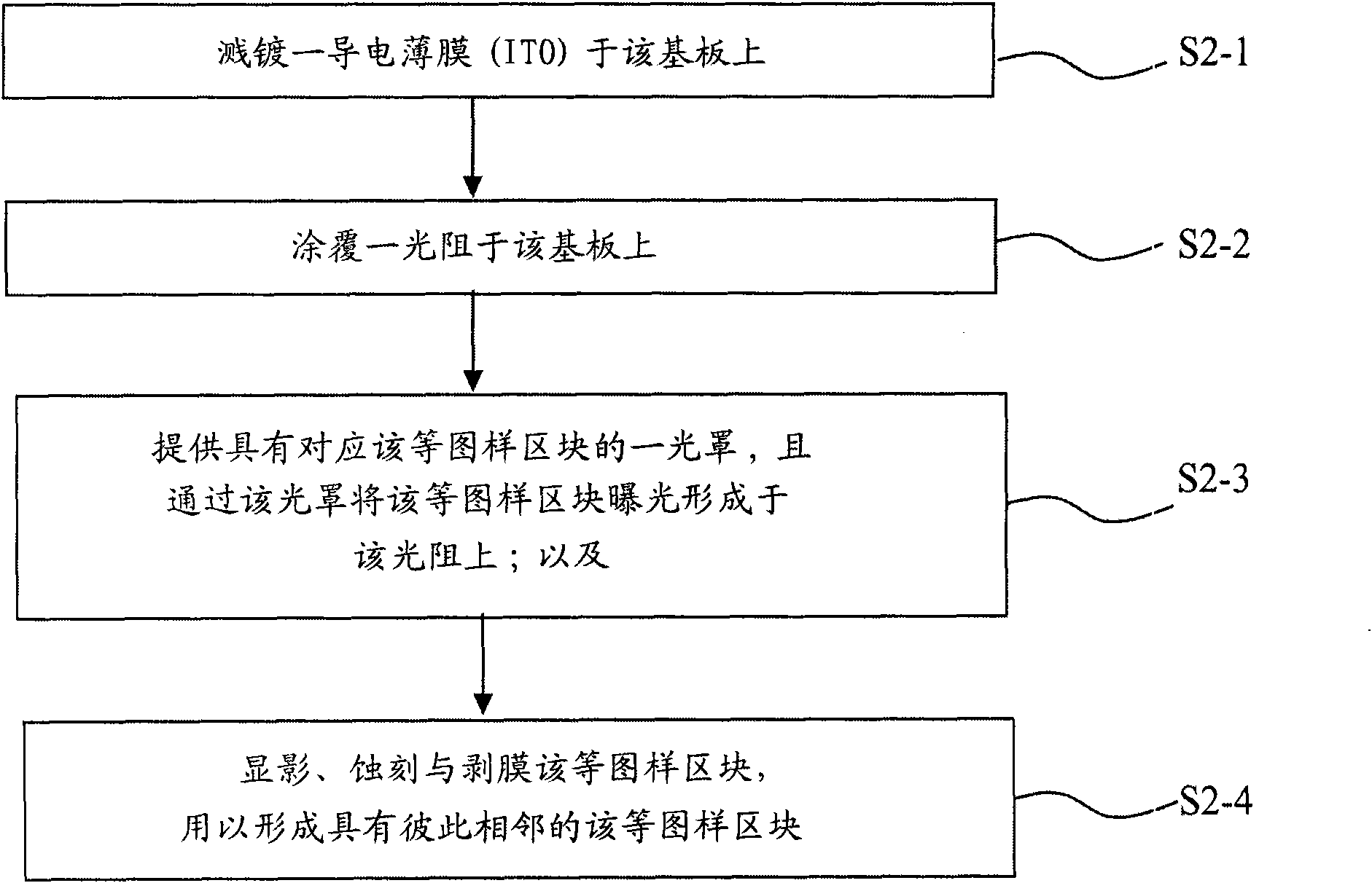
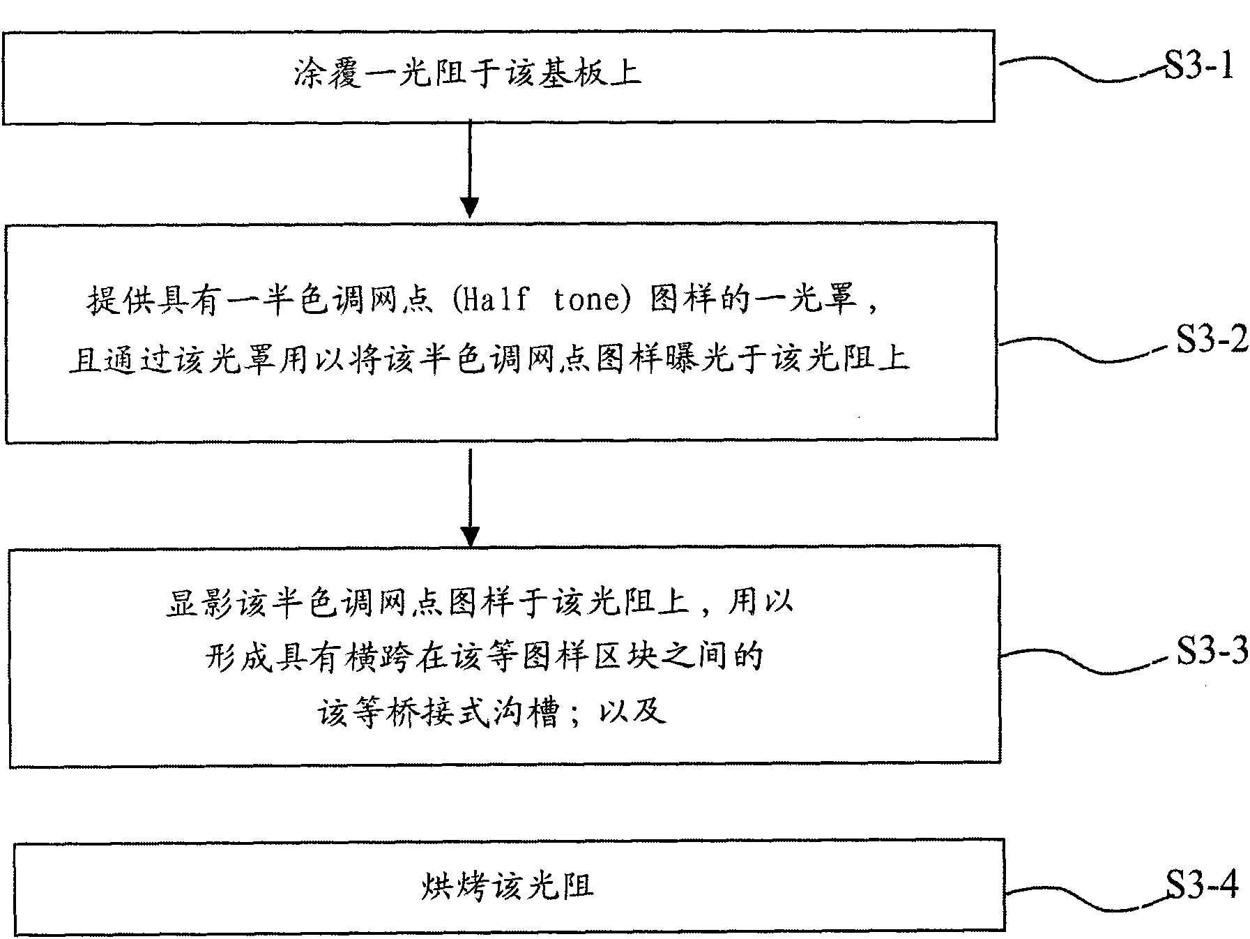
[0031] refer to Figures 1 to 5 , is a schematic flowchart of a bridging electrode arrangement method in an embodiment of the present invention. At figure 1 Among them, the steps of the bridge-type electrode layout method start at step S1 to provide a substrate; then step S2, forming a transparent conductive layer on the substrate, and the transparent conductive layer has a plurality of pattern blocks arranged adjacent to each other; and then Step S3, forming an alignment layer on the substrate, and the alignment layer has a plurality of bridging grooves for straddling between the pattern blocks; then step S4, forming a conductive layer on the substrate , and the conductive layer has a plurality of electrical wires respec...


PUM


Abstract

The invention relates to an arrangement method and a structure of a bridge electrode. The arrangement method of the bridge electrode comprises the following steps of: providing a substrate; forming a transparent conductive layer on the substrate, wherein the transparent conductive layer is provided with a plurality of pattern blocks which are arranged adjacent to each other; forming an alignment film layer on the substrate, wherein the alignment film layer is provided with a plurality of bridge grooves used for crossing among the plurality of pattern blocks; forming a conductive layer on the substrate, wherein the conductive layer is provided with a plurality of electrical conductors which are respectively arranged on the plurality of bridge grooves, the plurality of electrical conductorsof the conductive layer are formed by an optical compensation photomask together with over exposure or over development; and forming a protective layer on the substrate, wherein the protective layer is used for increasing optical transmittance and protecting the substrate, the transparent conductive layer, the alignment film layer and the conductive layer.

Description

technical field [0001] The present invention relates to an electrode layout method and its structure, especially using a special photomask to form a bridging groove on an insulating unit, so that the wires placed in the bridging groove are not likely to cause poor overall yield due to subsequent manufacturing processes. The layout method and structure of the bridging electrodes. Background technique [0002] In the known technology, in the manufacturing process of the capacitive touch panel, electrodes with two different axes are formed on the substrate, and an insulating layer is formed again on the electrodes of one axis to provide the electrodes of the other axis. The electrodes are electrically connected through metal wires provided on the insulating layer. [0003] However, the metal wires traditionally disposed on the insulating layer may be damaged in the subsequent manufacturing process, making the conduction impossible, thereby causing a decline in the production y...

Claims


Application Information

Patent Timeline
IPC IPC(8): G06F3/044
Inventor 范莉立
Owner 范莉立
Why Eureka
Try Eureka