Power strip and electric power measurement system
A technology of power board and current measurement, which is applied in the direction of electric power measurement through current/voltage, electric power measurement by using electromagnetic effect devices, and measurement devices, which can solve the problem of not being able to display the amount of power and not being able to measure the power of each electronic device separately Consumption and other issues
- Summary
- Abstract
- Description
- Claims
- Application Information
AI Technical Summary
Problems solved by technology
Method used
Image


Examples
no. 1 example
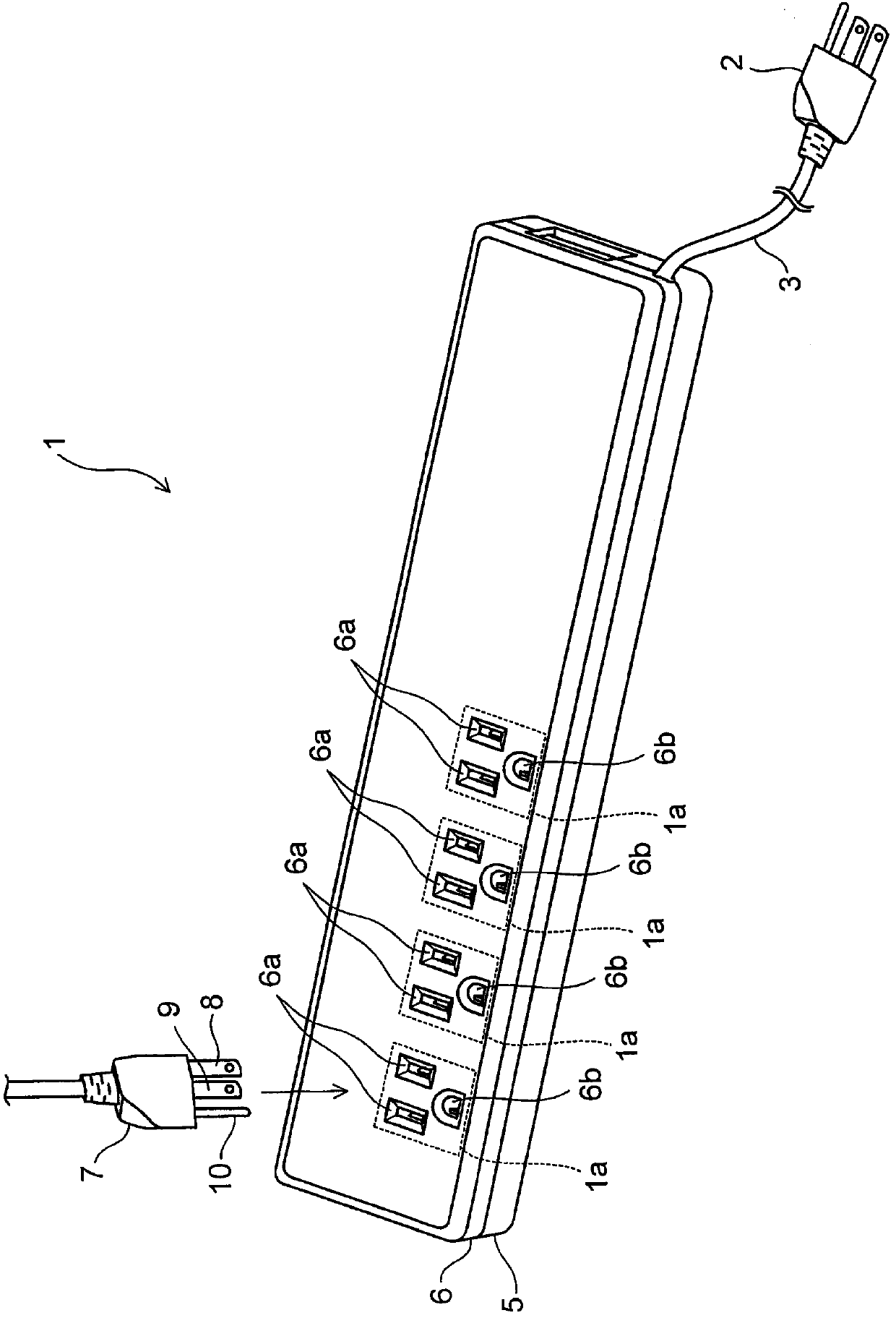
[0050] figure 1 is an external view of the power board 1 according to the first embodiment.
[0051] The power strip 1 is used to distribute AC power to a plurality of outlets 1a. AC power is supplied by the power plug 2 and the power cord 3 . In addition, the power board 1 has an upper cover 6 and a lower cover 5 which are made of resin and are screwed to each other.
[0052] A plurality of pairs of first openings 6 a and second openings 6 b corresponding to the plurality of sockets 1 a are formed in the upper cover 6 . Each pair of first opening 6a and second opening 6b allows an external power plug 7 to be inserted thereinto.
[0053] Each first opening 6a has a generally rectangular planar shape so as to allow a corresponding one of the blades 8 and 9 of the power plug 7 to be inserted thereinto. In addition, each second opening 6b has a substantially semicircular planar shape so as to allow the ground terminal 10 to be inserted thereinto.
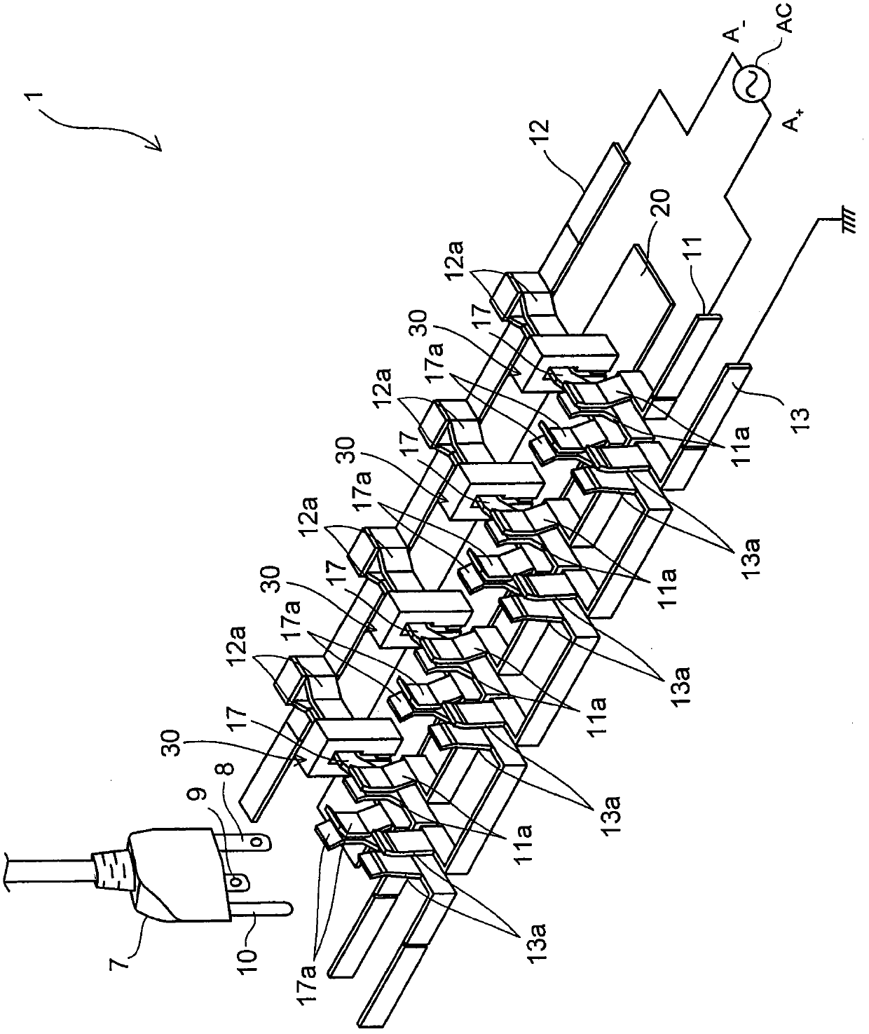
[0054] figure 2 is an ex...
no. 2 example
[0110] In this embodiment, a preferred positional relationship between the magnetic core 21 and the Hall element 22 is described.
[0111] Figure 10 is a perspective view for describing a simulation performed by the inventors of the present application.
[0112] Such as Figure 10 As shown, the magnetic field strength on the gap surface 21b of the magnetic core 21 facing the gap 21a was simulated.
[0113] Figure 11A with Figure 11B The simulation results of the magnetic field strength are shown respectively.
[0114] Figure 11A The distance W between the distribution bar 17 and the Hall element 22 1 different from Figure 11B The distance W between the distribution bar 17 and the Hall element 22 2 . Figure 11A The Hall element 22 in the Figure 11B Compared with the Hall element 22 in , it is arranged at a position closer to the distribution bar 17 .
[0115] Such as Figure 11A with Figure 11B As shown, it has been verified that the magnetic field strength...
no. 3 example
[0123] The difference between this embodiment and the first embodiment is only the form of the distribution bar 17, and the other structures of this embodiment are the same as those of the first embodiment.
[0124] Figure 12 is a perspective enlarged view of the distribution bar 17 and the second bus bar 12 according to the present embodiment.
[0125] Such as Figure 12 As shown, the distribution bar 17 is inserted between the pair of holders 12a of the second busbar 12 during assembly. At this time, preferably, portions of the distribution bars 17 held between the holders 12 a are chamfered in advance, thereby forming chamfered portions 17 g at corners of the distribution bars 17 . In this configuration, the chamfered portion 17g is allowed to come into sliding contact with the holders 12a, thereby allowing the distribution bar 17 to be smoothly and easily inserted between the pair of holders 12a during assembly.
[0126] The method of forming the chamfered portion 17g ...
PUM
 Abstract
Description
Claims
Application Information
 - R&D
- Intellectual Property
- Life Sciences
- Materials
- Tech Scout
- Unparalleled Data Quality
- Higher Quality Content
- 60% Fewer Hallucinations
Browse by: Latest US Patents, China's latest patents, Technical Efficacy Thesaurus, Application Domain, Technology Topic, Popular Technical Reports.
© 2025 PatSnap. All rights reserved.Legal|Privacy policy|Modern Slavery Act Transparency Statement|Sitemap|About US| Contact US: help@patsnap.com