Electrical connector for inflatable high voltage electrical appliance
A technology for electrical connectors and high-voltage electrical appliances, which is applied in the direction of connection, installation of connection components, and parts of connection devices, etc. It can solve the problems of high welding process requirements, time-consuming and laborious, and waste rework, so as to improve safety and reliability and ensure insulation. Performance, the effect of good pressure resistance
- Summary
- Abstract
- Description
- Claims
- Application Information
AI Technical Summary
Problems solved by technology
Method used
Image
Examples
Embodiment 1
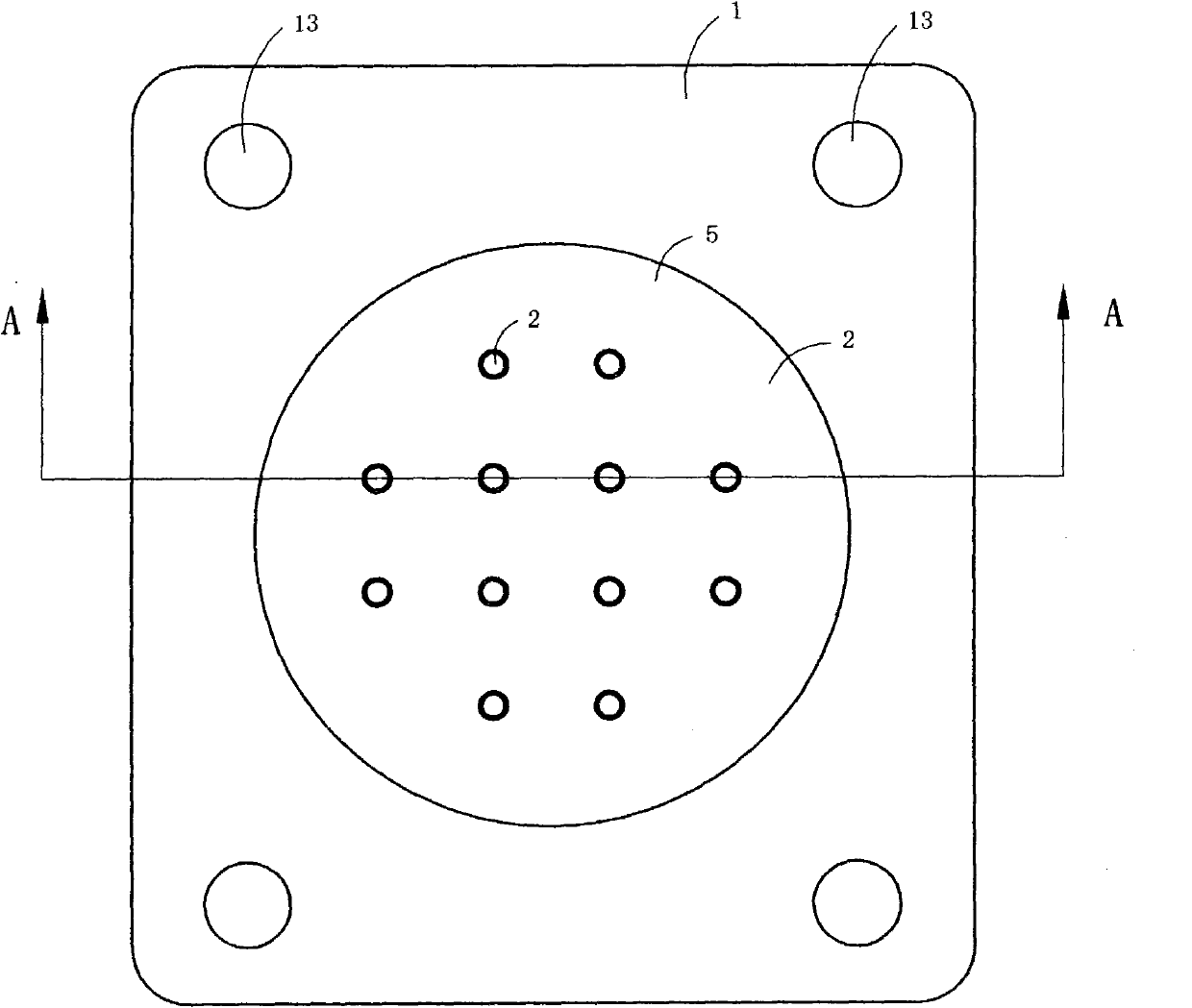
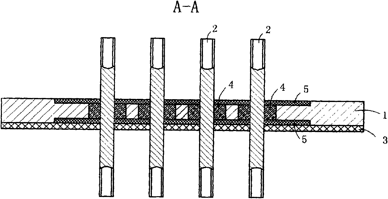
[0028] Figure 1 to Figure 3 A first embodiment of the invention is shown in which, figure 1 It is a structural schematic diagram of the first structure of the present invention; figure 2 for figure 1 Sectional view along line A-A; image 3 for figure 1 A schematic diagram of the structure of the substrate in the electrical connector shown.
[0029] The present invention is an electrical connector for an inflatable high-voltage electrical appliance, see Figure 1 to Figure 3 , including a rectangular plate-shaped stainless steel substrate 1 provided with mounting holes 13 at four corners and twelve terminal posts 2 arranged on the substrate 1 .
[0030] Twelve circular through-holes 11 are provided on the metal substrate 1, and a groove 12 is provided on both sides of the substrate, and the openings at both sides of each through-hole 11 are located in the corresponding grooves 12; The terminal 2 is located in the center of a corresponding through hole 11 ; an insulating...
Embodiment 2
[0036] Figure 4 It is a structural schematic diagram of the second structure of the present invention, showing the second specific implementation manner of the present invention.
[0037] This embodiment is basically the same as Embodiment 1, the difference is: see Figure 4 , the outer wall of the elastic sealing layer 3 is provided with two annular elastic protruding rings 31 . This structure can further ensure the airtightness between the substrate and the electrical housing.
Embodiment 3
[0039] Figure 5 It is a structural schematic diagram of the third structure of the present invention, showing the third specific implementation manner of the present invention.
[0040] This embodiment is basically the same as Embodiment 1, the difference is: see Figure 5 , both sides of the substrate 1 are fixed with an elastic sealing layer 3 as a sealing surface by injection molding or compression molding, and one end of the same side of the terminal post 2 and the elastic sealing layer 3 protrudes from the elastic sealing layer 3.
[0041] The above embodiments 1 to 3 have positive effects: (1) In the above embodiments 1 to 3, the substrate 1 is provided with a plurality of through holes 11, and each terminal post 2 is located in a corresponding through hole 11; the outer wall of each terminal 2 and the inner wall of the through hole 11 are filled with insulating material to form a ring-shaped insulator 4, and the two ends of each terminal 2 protrude from the ring-shap...
PUM
 Abstract
Description
Claims
Application Information
 - R&D
- Intellectual Property
- Life Sciences
- Materials
- Tech Scout
- Unparalleled Data Quality
- Higher Quality Content
- 60% Fewer Hallucinations
Browse by: Latest US Patents, China's latest patents, Technical Efficacy Thesaurus, Application Domain, Technology Topic, Popular Technical Reports.
© 2025 PatSnap. All rights reserved.Legal|Privacy policy|Modern Slavery Act Transparency Statement|Sitemap|About US| Contact US: help@patsnap.com


