
Bidirectional low-capacitance surge protection device

A surge protector and low-capacitance technology, applied in the field of bidirectional low-capacitance surge protection devices, can solve problems such as protection effect discount

Active Publication Date: 2015-01-21
SHANGHAI CHANGYUAN WAYON MICROELECTRONICS
View PDF5 Cites 0 Cited by
  • Summary
  • Abstract
  • Description
  • Claims
  • Application Information

AI Technical Summary

Problems solved by technology

[0004] Although Thyristor, GDT, MOV, and transient voltage suppressor (Transient Voltage Suppressor, TVS) have been widely used in various protection fields as an effective surge / ESD protection device, they cannot etc. have complete advantages, so that the protection scheme often adopts a compromise method to design
This greatly reduces the protective effect

Method used


Image

  • Bidirectional low-capacitance surge protection device
  • Bidirectional low-capacitance surge protection device
  • Bidirectional low-capacitance surge protection device

Examples


Embodiment 1

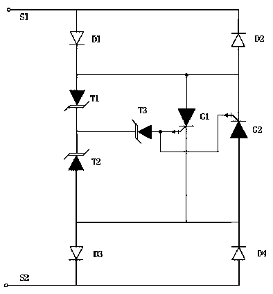
[0055] see figure 1As shown in the circuit structure diagram of the bidirectional low-capacitance surge protector in Embodiment 1 of the present invention, a bidirectional low-capacitance surge protector is composed of a first PIN tube D1, a second PIN tube D2, a third PIN tube D3, The fourth PIN tube D4, the first TVS tube T1, the second TVS tube T2, the third TVS tube T3, the first GTO tube G1 and the second GTO tube G2 constitute two-end components, wherein,

[0056] The anode of the first PIN tube D1 is connected to the cathode of the second PIN tube D2 as the first terminal S1 of the device;

[0057] The cathode of the first PIN tube D1 is connected to the anode of the first TVS tube T1, and is connected to the anode of the first GTO tube G1, the cathode of the second GTO tube G2, and the anode of the second PIN tube D2;

[0058] The cathode of the first TVS tube T1 is connected to the cathode of the second TVS tube T2, and is connected to the cathode of the third TVS tu...

Embodiment 2

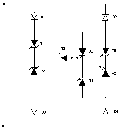
[0067] As an improvement of the present invention, the bidirectional low-capacitance surge protection device is improved, please refer to image 3 As shown in the circuit structure diagram of Embodiment 2 of the present invention, a fourth TVS tube T4 is added between the cathode of the first GTO tube G1 and the cathode of the fourth PIN tube D4, and between the cathode of the second GTO tube G2 and the second PIN tube D2 The fifth TVS tube T5 is added between the anodes, and the other connection methods remain unchanged, that is, the cathode of the first PIN tube D1 is connected to the anode of the fifth TVS tube T5, and the cathode of the fifth TVS tube T5 is connected to the cathode of the second GTO tube G2 connected; the cathode of the first GTO tube G1 is connected to the cathode of the fourth TVS tube T4, and the anode of the fourth TVS tube T4 is connected to the anode of the second TVS tube T2. In this way, a bidirectional low-capacitance surge protector with a contro...


PUM


Abstract

The invention provides a bidirectional low-capacitance surge protection device, wherein the anode of a first PIN tube is connected with the cathode of a second PIN tube, and is used as a leading-out end S1; the anodes of a first TVS (Transient Voltage Suppressor) tube and a first GTO (Gate Turn Off Thyristor) tube, the cathode of a second GTO tube and the anode of the second PIN tube are respectively connected with the cathode of the first PIN tube; the cathode of the first TVS tube is connected with the cathodes of the second TVS tube and a third TVS tube; the gates of the first GTO tube and the second GTO tube are respectively connected with the anode of the third TVS tube; the cathode of the first GTO tube, the cathode of a fourth PIN tube, the anode of the second GTO tube and the anode of a third PIN tube are respectively connected with the anode of the second TVS tube; and the cathode of the third PIN tube is connected with the anode of a fourth PIN tube, and is used as a second leading-out end of the device. The invention has the advantages that the low-capacitance characteristic of the PIN tubes and the high-current discharging capability of the GTO tubes are utilized to realize the bidirectional low-capacitance surge protection device; breakover voltage control and lower operating range control of residual voltage are realized on the basis of the connected TVS tubes; and the breakover voltage and the residual voltage after breakover of the device can be effectively controlled by adjusting the breakdown voltage of the TVS tubes.

Description

technical field [0001] The invention relates to the field of semiconductor devices, in particular to the field of semiconductor overvoltage protection devices, and is a novel bidirectional low-capacity surge protection device. Background technique [0002] With the gradual adoption of new interface standards in the communication field, such as VDSL+, USB3.0, etc., the improvement of transmission speed will further put forward new requirements for the capacitance of protection devices. While ensuring high surge capacity, reducing device capacitance has become a common trend . [0003] In the past few decades, the microelectronics manufacturing process with silicon as the main processing material has changed from the initial few micron technology to the current 45nm, and the integration level of integrated circuit chips has become higher and higher, and the cost has become lower and lower. As the size of the chip shrinks, the overvoltage capability that the circuit can withst...

Claims


Application Information

Patent Timeline
Patent Type & Authority Patents(China)
IPC IPC(8): H02H9/04
Inventor 张关保苏海伟王永录叶力吴兴农
Owner SHANGHAI CHANGYUAN WAYON MICROELECTRONICS
Learn More