Low-capacitance large-surge protective circuit

A technology of surge protection and low capacitance, which is applied in the field of semiconductor overvoltage protection devices, can solve the problems of large PCB space occupation, high integration of differential common mode, complex wiring, etc., and achieve large surge capacity, low clamping, and low The effect of PCB space

Inactive Publication Date: 2013-04-24
李怀东
View PDF7 Cites 0 Cited by
  • Summary
  • Abstract
  • Description
  • Claims
  • Application Information

AI Technical Summary

Problems solved by technology

[0004] The purpose of the present invention is to overcome the defects in the prior art that there are a large number of required electronic components, various types, complicated wiring, and large PCB space occupation, and provide an integrated low-capacitance surge protection circuit for the protected system. Not only can it avoid damage to the protected system by transient voltages such as surges and ESD, but it also has the advantages of simple wiring, low capacitance, low clamping, large surge protection capabilities, and highly integrated differential common mode

Method used


Image

  • Low-capacitance large-surge protective circuit
  • Low-capacitance large-surge protective circuit
  • Low-capacitance large-surge protective circuit

Examples


Embodiment 1

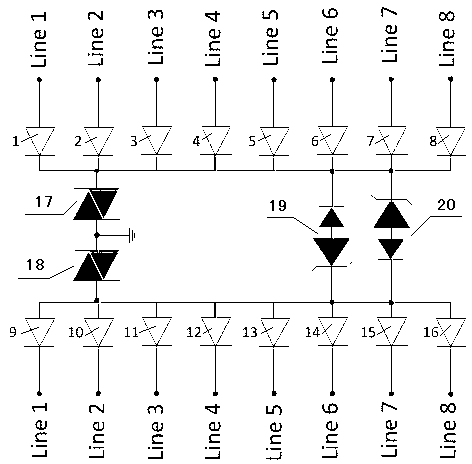
[0020] Such as figure 1 As shown, a low-capacitance surge protection circuit is composed of 16 decapacitating diodes, 2 low-voltage TVS diodes and 2 bidirectional discharge tubes. The first decapacitating diode (1) to the eighth decapacitating diode (8) The cathode is connected to one end of the first bidirectional discharge tube (17), and connected to the anode of the first low-voltage TVS tube (19) and the cathode of the second low-voltage TVS tube (20), and the first decapacity tube (1) to the eighth The anodes of the capacitance reduction diodes (8) are respectively connected to line 1 to line 8 in turn. The anodes of the ninth decapacitating diode (9) to the sixteenth decapacitating diode (16) are connected to one end of the second bidirectional discharge tube (18), and connected to the cathode of the first low voltage TVS tube (19) and the second low voltage TVS The anodes of the tube (20) are connected, the cathodes of the ninth decapacitating tube (9) to the sixteenth...

Embodiment 2

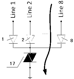
[0026] Such as Figure 6 As shown, a low-capacitance surge protection circuit is composed of 8 capacitance-reducing diodes, 2 low-voltage TVS diodes and 2 bidirectional discharge tubes to achieve 4-way differential common-mode protection. The cathodes of the first decapacitating diode (1) to the fourth decapacitating diode (4) are connected to one end of the first bidirectional discharge tube (17), and connected to the anode of the first low voltage TVS tube (19) and the second low voltage TVS tube The cathodes of (20) are connected, and the anodes of the first decapacitating diode (1) to the fourth decapacitating diode (4) are respectively connected to line 1 to line 4 in turn. The anodes of the fifth decapacitating diode (5) to the eighth decapacitating diode (8) are connected to one end of the second bidirectional discharge tube (18), and connected to the cathode of the first low voltage TVS tube (19) and the second low voltage TVS tube The anodes of (20) are connected, th...


PUM


Abstract

The invention relates to a low-capacitance large-surge protective circuit. The low-capacitance large-surge protective circuit is composed of 2n (n is an integer larger than or equal to 2 and smaller than or equal to 16) capacitance-reducing diodes, two low-voltage transient voltage suppressors (TVS) and two bothway discharge tubes. Negative poles of the capacitance-reducing diodes from the first to the nth are connected with one end of a first bothway discharge tube and are connected with a positive pole of a first low-voltage TVS and a negative pole of a second low-voltage TVS. Positive poles of the capacitance-reducing diodes from the first to the nth are respectively connected with lines from a line 1 and a line n. Positive poles of the capacitance-reducing diodes from the (n+1) th to 2nth are connected with one end of a second bothway discharge tube and are connected with a negative pole of a first low-voltage TVS and a positive pole of a second low-voltage TVS. Negative poles of the capacitance-reducing diodes from the (n+1)th to 2nth are respectively connected with the lines from the line 1 and the line n in sequence. The low-capacitance large-surge protective circuit overcomes the shortcomings that needed electronic components are large in amount, various in kind and complex in wiring, and occupied space in a printed circuit board (PCB) is large. Meanwhile, the low-capacitance large-surge protective circuit is simple in wiring, and has a low capacitance, low clamping and large surge protection ability, and has the advantage that a differential mode and a common mode are highly integrated.

Description

technical field [0001] The invention relates to the field of semiconductor overvoltage protection devices, in particular to a low-capacity large surge protection circuit, which is an emergency protection circuit used to limit overvoltage without cutting off the circuit. Background technique [0002] With the increase of the communication rate, the protection requirements of the data communication interface are getting higher and higher. The protection schemes that can meet the reliability test standards such as K20 and K21 often involve more protection components and larger PCB space. The situation that the main control IC chip of the circuit is burned due to the matching difference between the protection components occurs frequently. [0003] There are many components that can be used for surge protection, such as Thyristor, GDT, MOV, transient voltage suppressor (Transient Voltage Suppressor, TVS) and so on. For example, the patent application CN 201210172902.4 uses elect...

Claims


Application Information

Patent Timeline
IPC IPC(8): H02H9/04
Inventor 李怀东
Owner 李怀东
Why Eureka
Try Eureka