Low-capacitance low-clamping overvoltage protection device

An overvoltage protection device and low capacitance technology, applied in the field of low-clamp transient voltage suppression devices, low-capacity low-clamp overvoltage protection devices, can solve the problem that low capacitance and high surge cannot be obtained at the same time, low clamp and Problems such as the coexistence of high capacitance achieve the effect of high surge capability and low capacitance for differential applications

Active Publication Date: 2015-01-07
SHANGHAI CHANGYUAN WAYON CIRCUIT PROTECTION CO LTD
View PDF5 Cites 0 Cited by
  • Summary
  • Abstract
  • Description
  • Claims
  • Application Information

AI Technical Summary

Problems solved by technology

[0004] Although the transient voltage suppressor has been widely used in various protection fields as an effective surge / ESD protection device, based on the above considerations, before introducing the transient voltage suppressor into the circuit design, we cannot sacrifice the signal of the system At the expense of integrity and system security, introduce various existing suppressors into interface protection
[0005] There are two major problems in traditional Zener TVS tubes, one is that low capacitance and high surge cannot be obtained at the same time, and the other is that the problem of coexistence of low clamping and high capacitance has not been resolved

Method used


Image

  • Low-capacitance low-clamping overvoltage protection device
  • Low-capacitance low-clamping overvoltage protection device
  • Low-capacitance low-clamping overvoltage protection device

Examples


Embodiment 1

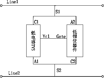
[0067] see figure 1 As shown in the principle block diagram of the circuit structure of the present invention, the low-capacity and low-clamp overvoltage protection device is composed of a group of low-capacity TVS tubes and low-clamp tubes. Among them, the low-capacitance TVS tube has three connection terminals, namely the cathode C1, the anode A1 and the clamp output terminal Vc1; the low clamp tube also has three connection terminals, the cathode C2, the anode A2 and the gate control terminal Gate.

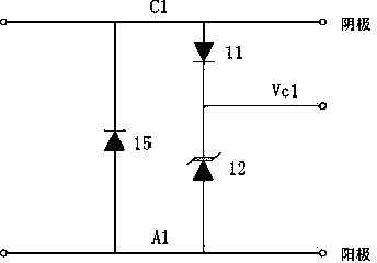
[0068] see figure 2 As shown in the circuit structure diagram of the low-capacitance TVS device of the present invention, the low-capacity TVS tube is composed of a first PIN diode 11, a second PIN diode 15 and a TVS tube 12, wherein,

[0069] The anode of the first PIN diode 11 is connected to the cathode of the second PIN diode 15 to form the cathode C1 of the low capacitance TVS tube;

[0070] The cathode of the first PIN diode 11 is connected to the cathode of the TVS tu...

Embodiment 2

[0082] As an improvement of Embodiment 1 of the present invention, please refer to Figure 7 As shown in the circuit structure diagram of two sets of low-capacitance and low-clamp overvoltage protection devices in Embodiment 2 of the present invention, they are three-terminal low-capacitance and low-clamp overvoltage protection devices. This embodiment is the structure of Embodiment 1 in which two groups are mirror images of each other. A three-terminal low-capacitance low-clamp overvoltage protection device is formed with the low-clamp tube as the mirror axis. The device connection terminals after mirror connection correspond to the connection terminals S1a and Connect terminal S2a, and connect terminal S2a of the mirrored three-terminal low-capacitance low-clamping overvoltage protection device and the connecting terminal S2 of the original device as a common terminal, and the same connecting line (also called S2 connecting terminal), three The connection terminals are respe...

Embodiment 3

[0091] see Figure 8 It is a group of low-capacity low-clamp overvoltage protection device circuit structure diagram and Figure 9 It is shown in the circuit structure diagram of two groups of low-capacitance and low-clamp overvoltage protection devices in Embodiment 3 of the present invention, Figure 8In the figure, the structure inside the dotted line box is an improved structure. The improved low-capacitance TVS tube is composed of a PIN diode and a TVS tube. The corresponding connecting terminal electrodes remain unchanged. Figure 4 The improvement is to remove the second resistor of the low-capacitance TVS tube, and the other connection relationships remain unchanged.

[0092] Figure 8 Middle: The improved low-capacitance TVS tube is composed of a PIN diode 11' (or 11c) and a TVS tube 12' (or 12c), wherein the anode of the PIN diode 11' (or 11c) is drawn out to form a low-capacitance TVS tube The cathode of the PIN diode 11' (or 11c) is connected to the cathode of t...


PUM


Abstract

The invention relates to a low-capacitance low-clamping overvoltage protection device. The invention is characterized in that the overvoltage protection device is formed by connecting a low-capacitance TVS (Transient Voltage Suppressor) tube and a low-clamping tube in parallel, the low-capacitance TVS tube is used for low-capacitance path and primary surge / ESD (Electronic Static Discharge) protection, and the low-clamping tube is used to lower the clamping voltage of the whole device, wherein the cathode of low-capacitance TVS tube is connected with the anode of the low-clamping tube, the anode of the low-capacitance TVS tube is connected with the cathode of the low-clamping tube and the clamping output end of the low capacitance TVS tube is connected with the gate control end of the low-clamping tube. The invention has the advantages that a low capacitance low clamping TVS device is formed on the basis of the low capacitance characteristics of a PIN (positive-intrinsicnegative diode) tube and low pass-state voltage drop characteristic of the low clamping tube, the problem of the traditional multi-level protection which can not meet the requirement of low capacitance and low residual voltage of high-speed data can be overcome; meanwhile, a three-terminal low-capacitance low-clamping TVS used for common-mode and differential-mode protection can be realized, and the capacitance of differential application is lower; and a low-clamping high-surging-capability two-way two-terminal VTS can be realized.

Description

technical field [0001] The invention relates to the field of semiconductor overvoltage protection devices, in particular to a low-capacity and low-clamp overvoltage protection device, which is a low-clamp transient voltage suppression device. Background technique [0002] In the past few decades, the microelectronics manufacturing process with silicon as the main processing material has changed from the initial few micron technology to the current 0.13μm technology, and the integration of integrated circuit chips has become higher and higher, and the cost has become lower and lower. As the size of the chip shrinks, the overvoltage capability that the circuit can withstand is gradually reduced, and the system will be more sensitive to external voltage fluctuations. This requires that the residual voltage of the protection device be controlled at very low level. [0003] At the same time, due to the continuous development of electronic application requirements, modern integra...

Claims


Application Information

Patent Timeline
Patent Type & Authority Patents(China)
IPC IPC(8): H02H9/04
Inventor 张关保苏海伟王永录叶力吴兴农
Owner SHANGHAI CHANGYUAN WAYON CIRCUIT PROTECTION CO LTD
Why Eureka
Try Eureka