Method and apparatus for reporting channel state information
A technology of channel state information and channel matrix, which is applied in the field of communication, can solve problems such as inapplicable multi-point coordinated transmission, and achieve the effect of reducing overhead and improving applicability
- Summary
- Abstract
- Description
- Claims
- Application Information
AI Technical Summary
Problems solved by technology
Method used
Image

Examples
Embodiment 1
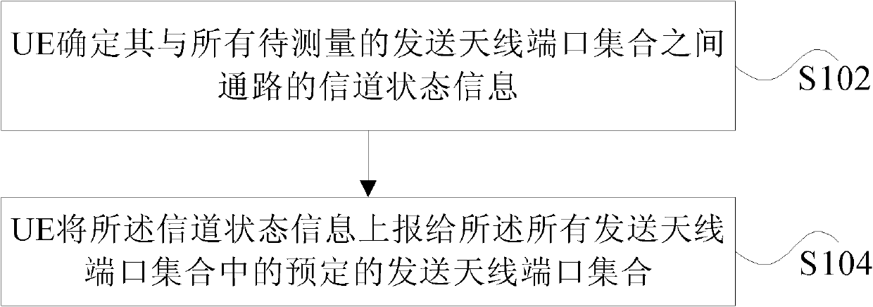
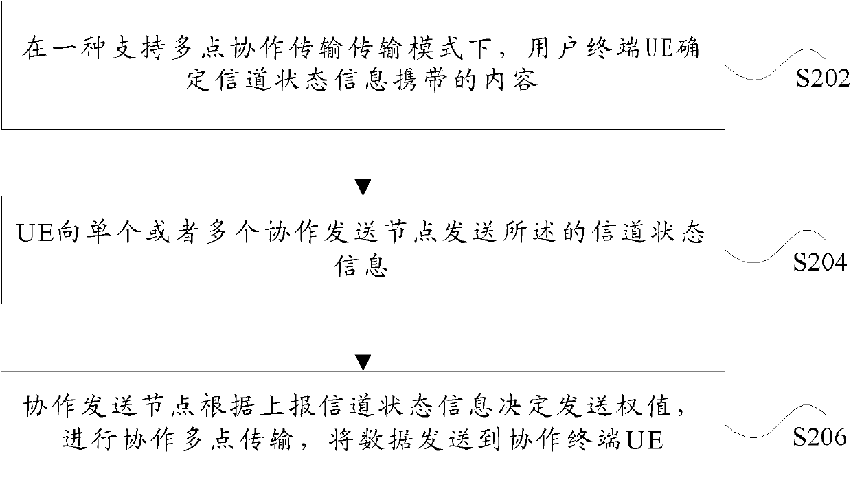
[0073] The UE reports the channel state information of the N transmit antenna port sets to the terminal to one transmit antenna port set in the N coordinated transmission points.
[0074] The M sets of transmitting antenna ports transmit data to the terminal through coordinated multi-point transmission, where the M sets of transmitting antenna ports are a subset of the N transmitting antenna port sets.
[0075] Wherein, N is a positive integer greater than or equal to 2, and M is a positive integer greater than or equal to 2 and less than or equal to N.
[0076] Preferably, the set of transmit antenna ports is a base station or RRH.
[0077] Preferably, for a user terminal, there is one set of first-type transmit antenna ports in the N transmit antenna port sets, and the rest are second-type transmit antenna port sets. Wherein, the first type of sending antenna port set is the sending node that receives the channel state information reported by the terminal, and the second ty...
Embodiment 2
[0090] The difference between this preferred embodiment 2 and preferred embodiment 1 is that the channel state information feedback of the second type of transmitting antenna port set is different, so this preferred embodiment 2 only describes the content of the channel state information of the second type of transmitting antenna port set, other Same as preferred embodiment one.
[0091] The channel state information of the second type of transmit antenna port set includes at least: M2 pieces of precoding matrix index information PMI, and N2 pieces of channel quality indication information, where M2 and N2 are positive integers greater than or equal to 1.
[0092] Corresponding to the above case 2, in the second preferred embodiment, M2=N-1, M2 precoding matrix index PMI includes N-1 channel precoding matrix index cPMI, each cPMI corresponds to a second type of transmit antenna port set channel state information to the terminal. And, each cPMI corresponds to a set of transmit...
Embodiment 3
[0097] The difference between this preferred embodiment 3 and preferred embodiment 1 is that the channel state information feedback of the second type of transmitting antenna port set is different, so this preferred embodiment 3 only describes the content of the channel state information of the second type of transmitting antenna port set, other Same as preferred embodiment one.
[0098] Corresponding to the third case above, in the third preferred embodiment, M2=2 * (N-1), M2 precoding matrix index PMI includes N-1 best accompanying precoding matrix index BCI (Best companion indcator), each BCI corresponds to a second type of transmit antenna port set to the channel of the terminal State information, and each BCI is represented by a pair of indexes. And, each BCI corresponds to a set of transmit antenna ports, where M2=2 * (N-1).
[0099] Preferably, the best accompanying precoding matrix index BCI can be represented by a pair of precoding matrix indexes (i1, i2), which is...
PUM
 Abstract
Description
Claims
Application Information
 - Generate Ideas
- Intellectual Property
- Life Sciences
- Materials
- Tech Scout
- Unparalleled Data Quality
- Higher Quality Content
- 60% Fewer Hallucinations
Browse by: Latest US Patents, China's latest patents, Technical Efficacy Thesaurus, Application Domain, Technology Topic, Popular Technical Reports.
© 2025 PatSnap. All rights reserved.Legal|Privacy policy|Modern Slavery Act Transparency Statement|Sitemap|About US| Contact US: help@patsnap.com