

Obstacle detection alarm system and method
An obstacle and warning signal technology, which is applied in the field of obstacle detection and warning systems, can solve the problems of difficult erection, wrong distance estimation, and large amount of calculation of the system, and achieve the effect of reducing production costs and easy installation
- Summary
- Abstract
- Description
- Claims
- Application Information
AI Technical Summary
Problems solved by technology
Method used
Image

Examples
Embodiment Construction
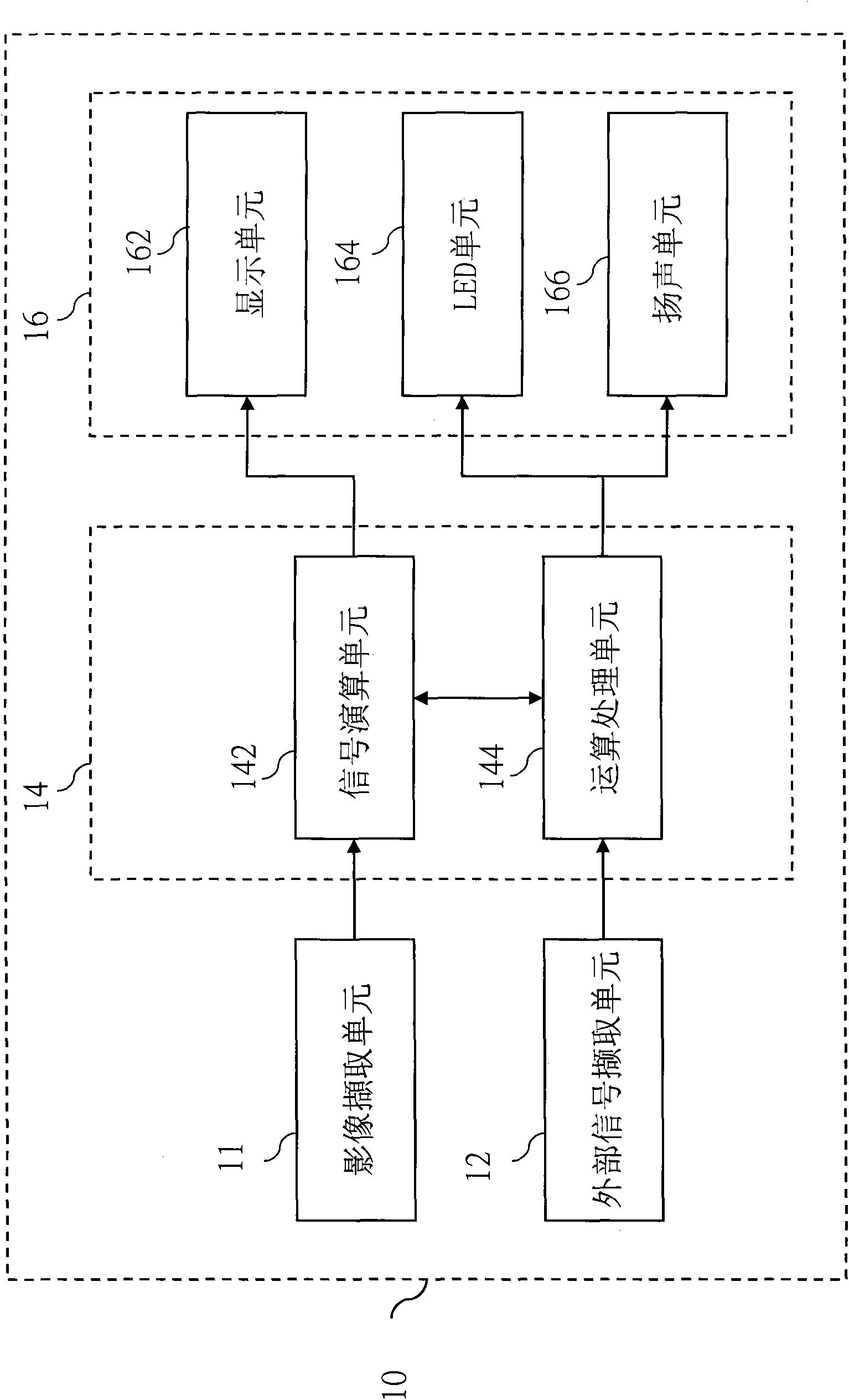
[0058] see figure 1 , illustrating the system architecture block diagram of the present invention, the image type obstacle detection and warning system 10 is electrically connected to the processing device 14 by at least one image capture unit 11, as a sensing element for capturing images, the image capture unit 11 can be used as Charge-coupled device (Charge-coupled Device, CCD) or complementary metal-oxide-semiconductor device (Complementary Metal-Oxide-Semiconductor, CMOS), the processing device 14 can be selectively electrically connected to at least one external signal acquisition unit 12 to Receive external signals such as vehicle speed signal, gear position signal or steering wheel angle for reference. The processing device 14 has at least one calculation processing unit 144 electrically connected to at least one signal calculation unit 142, wherein the calculation processing unit 144 can use such as central processing unit (Central Processing Unit, CPU), microprocessor...
PUM
 Abstract
Description
Claims
Application Information