Drill

A drill bit and drill diameter technology, which is applied in the direction of drill repair, twist drill, drill tool accessories, etc., can solve the problems of reduced chip discharge, outer edge corner defect, and larger cut-in, so as to achieve centripetal suppression, increase rigidity, Effect of improving discharge performance

Inactive Publication Date: 2011-08-31
OSG
View PDF1 Cites 13 Cited by
  • Summary
  • Abstract
  • Description
  • Claims
  • Application Information

AI Technical Summary

Problems solved by technology

[0005] However, the drill described in the above-mentioned Patent Document 1 is a two-edged drill with two helical flutes, and the amount of feed per one rotation exceeds 0.05D (5% of D) relative to the diameter D of the drill, especially in steel cutting. In the case of high-feed machining, the amount of cut per edge becomes large, and there are cases where chipping occurs due to insufficient cutting edge strength, so the stability is not good
In addition, when the thickness of the core is increased to increase the strength of the cutting edge, the thicker chips cut at high feed curl well in the flutes without being cut off, resulting in reduced chip discharge performance, which is prone to chip damage. damage due to blockage
On the other hand, in the case of the three-edge drill described in Patent Document 2, it is not necessary to provide the negative angle described in Patent Document 1 on the outer peripheral portion of the main cutting edge in order to prevent chipping during normal drilling. However, in the case of high-feed drilling, it will induce defects in the corners of the outer edge, and due to the small curling curvature of the chips, the chip discharge performance is not good in high-speed cutting and deep hole processing.

Method used


Image

  • Drill
  • Drill
  • Drill

Examples


Embodiment Construction

[0032] The invention is suitable for three-blade drill bits, and can also be applied to drill bits with four or more blades. The spiral groove is set to be twisted in the same direction as the rotation direction of the drill from the shank side, and chips are discharged to the shank side. The twist angle is appropriately set, for example, in the range of about 10°-50° . The material of the drill bit can use various tool materials such as cemented carbide, high-speed tool steel, and coating with hard coatings such as titanium aluminum nitride (TiAlN), titanium carbide nitride (TiCN), titanium nitride (TiN), diamond, etc. membrane. It is also possible to provide a fluid supply hole (oil injection hole) opened in the rear clearance surface of the front end so as to penetrate longitudinally in the axial direction.

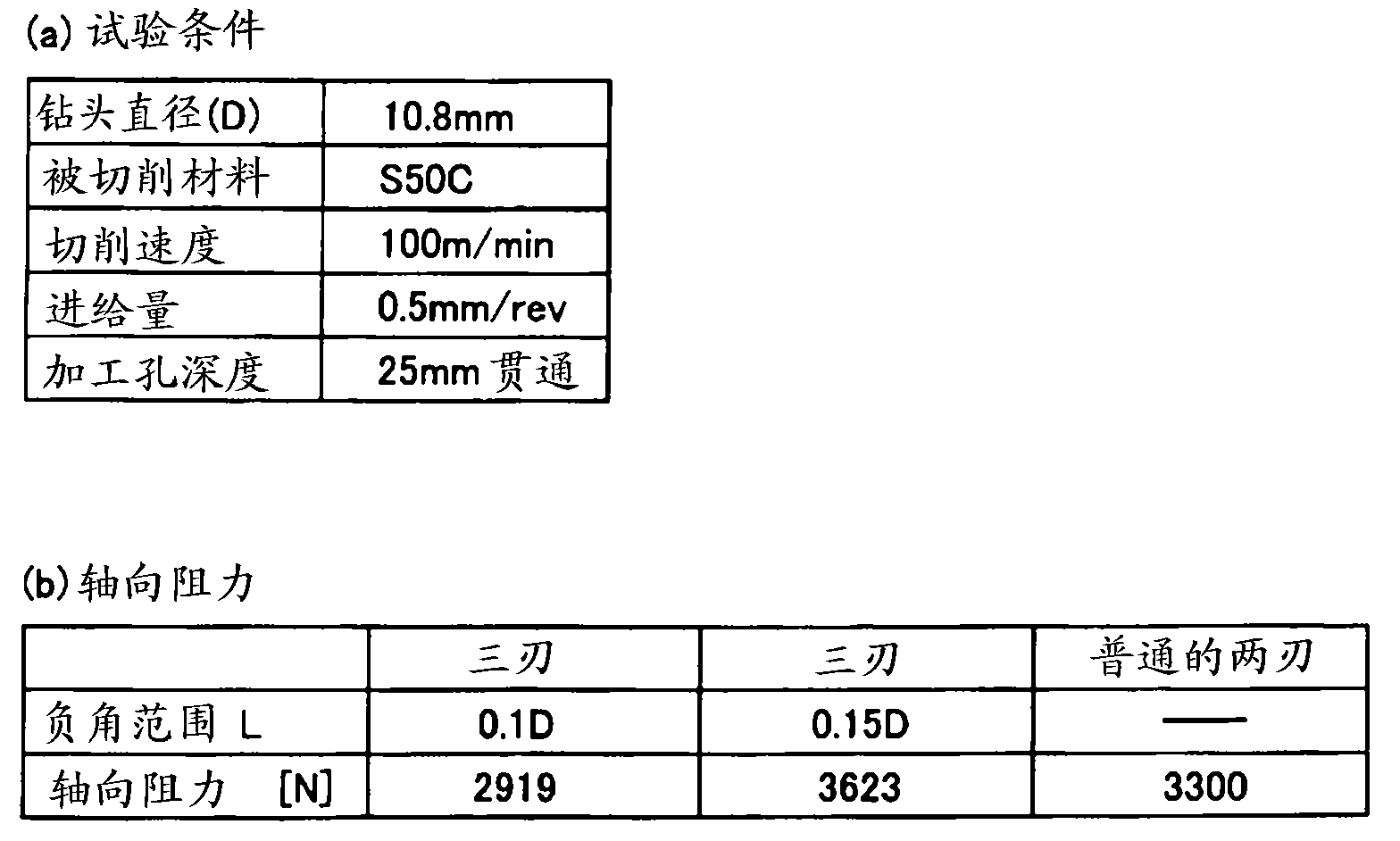
[0033] The drill bit of the present invention is particularly effective when the feed per revolution exceeds 5% of the drill diameter D, especially when the feed exceed...


PUM


Abstract

The present invention provides a drill in which three main cutting edges (14) are provided at equal angular intervals around a drill shaft center (O), and a negative angled part (20) with a radial rake angle (phi) of a negative value is provided along a circumference of the main cutting edge (14). In addition, the radial rake angle (phi) of the negative angled part (20) ranges -20 DEG <= phi < 0 DEG, and a negative angle range (L) is 0.1D or less with respect to a drill diameter (D) from a circumferential corner. A part toward the drill shaft center (O) from the part (20) is a concaved shape smoothly concaved oppositely to the drill rotation direction. Thus, cut chip discharging performance and rigidity of a tool or cutting edge strength can be improved with good balance while preventing cutting resistance and thrust resistance from increasing. This can lead to highly efficient machining by high feeding. In addition, the drill can be appropriately used for boring various kinds of materials to be cut such as cast iron requiring relatively high rigidity, normal steel, and aluminum alloy with low dischargeablity of cut chips.

Description

Technical field [0001] The invention relates to a drill bit, in particular to a drill bit capable of high-feed and high-efficiency processing. Background technique [0002] A drill bit as a rotary cutting tool for drilling is well known. In the drill bit, a plurality of spiral grooves are provided around the axis of the drill bit, and a main cutting groove is formed along each spiral groove on the portion of the spiral groove that is open at the front end of the drill bit. In addition, a thinning chisel edge that is smoothly connected to the main cutting edge is provided near the drill axis center of the drill tip. The drill described in Patent Document 1 is an example. On the outer peripheral portion of the main cutting edge, a negative corner portion with a negative radial rake angle when viewed from the tip side of the drill bit is provided at the outer corner. Within the initial predetermined range, the strength of the cutting edge near the corner of the outer edge can be in...

Claims


Application Information

Patent Timeline
Patent Type & Authority Applications(China)
IPC IPC(8): B23B51/00
CPCB23B2222/04B23B2251/18B23B2251/202B23B2251/406B23B2251/04B23B2222/14B23B2251/082B23B51/02B23B2251/14Y10T408/9097
Inventor 枡田典宏
Owner OSG
Why Eureka
Try Eureka