Two-dimensional barcode localization for camera based devices

A two-dimensional barcode and barcode technology, applied in computer parts, image analysis, image enhancement, etc., can solve problems such as error-prone

Inactive Publication Date: 2011-08-31
MICROSOFT CORP
View PDF3 Cites 9 Cited by
  • Summary
  • Abstract
  • Description
  • Claims
  • Application Information

AI Technical Summary

Problems solved by technology

This technique is error prone and suffers from usability and / or accessibility issues
Also, manual positioning is sometimes impossible, such as when the barcode is in the distance and the mobile phone lacks camera zoom

Method used


Image

  • Two-dimensional barcode localization for camera based devices
  • Two-dimensional barcode localization for camera based devices
  • Two-dimensional barcode localization for camera based devices

Examples


Embodiment Construction

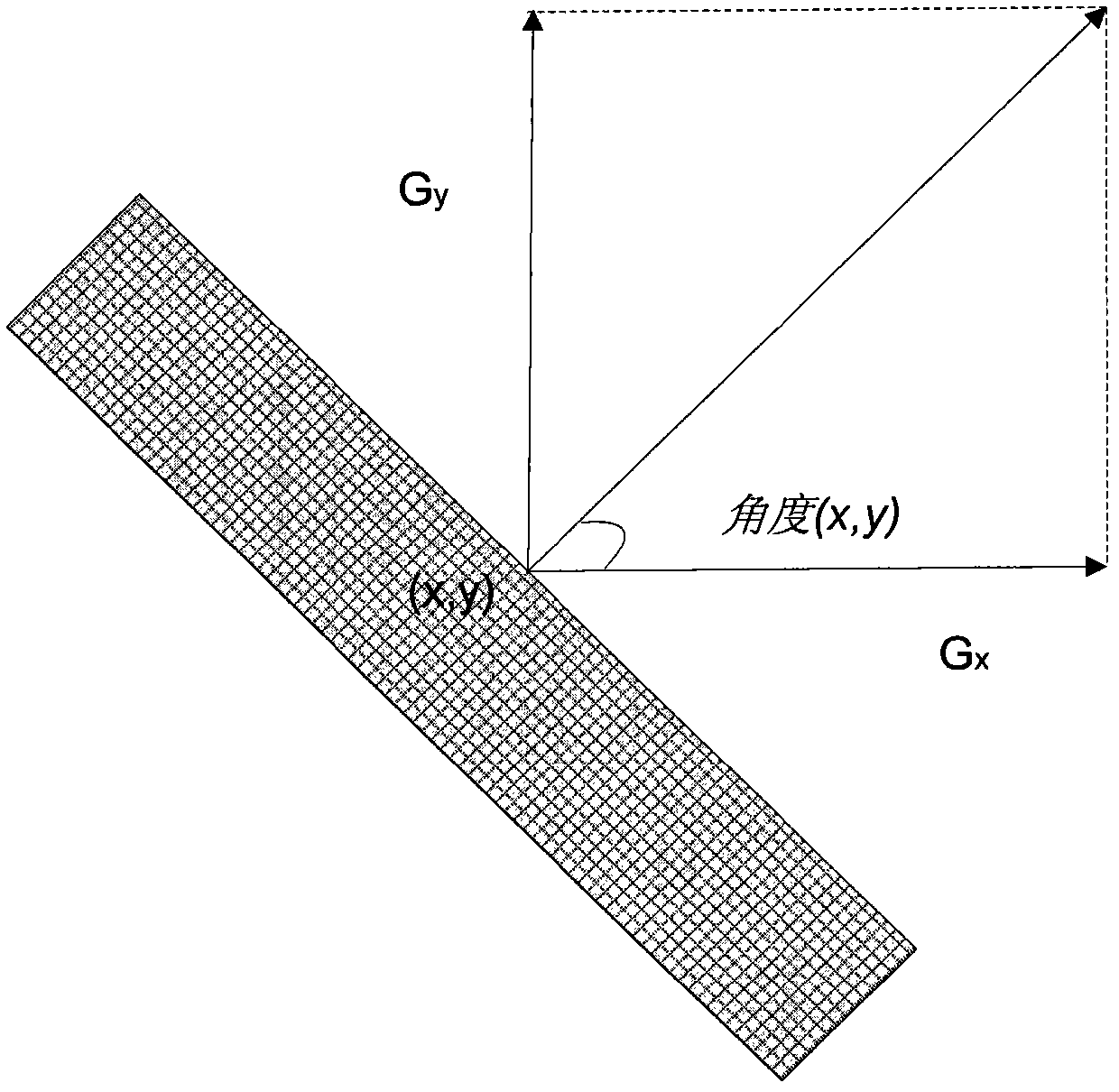
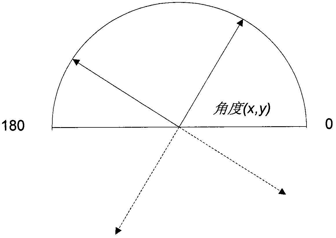
[0016] Aspects of the techniques described herein are generally directed to locating two-dimensional barcode symbols based on signatures collected from angular distribution analysis of the distribution of pixels of the barcode symbol; owned. While some of the examples described herein are directed to QR code barcode symbols, it should be understood that these are examples only. For example, other symbols, including other types of barcodes with identifiable signatures, could also benefit from similar positioning techniques. As such, the invention is not limited to any particular embodiment, aspect, concept, structure, function or example described herein. Rather, any of the embodiments, aspects, concepts, structures, functions, or examples described herein are non-limiting, and the invention can be implemented in various ways that provide benefits and advantages in computing and image processing in general use.

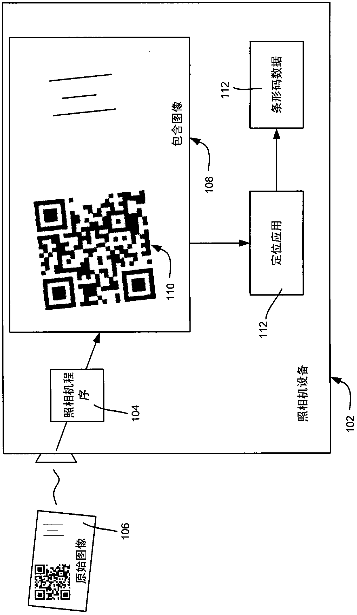
[0017] go to figure 1 , which shows a camera device 102 that ...


PUM


Abstract

Described is a technology in which a two-dimensional barcode symbol (e.g., a QR Code TM) is located within an image by looking for angular signatures that indicate a high density of generally vertical and/or horizontal angles. An image is divided into blocks of pixels. Angles are associated with each pixel, forming an angular signature for the block based on how many pixels are associated with each angle. The angular signatures indicate which blocks have pixels associated with mostly generally vertical and/or horizontal angles. A region with the largest number of blocks having such angular signatures is determined, and a bounding box for the barcode symbol grown from that region block by evaluating nearby blocks to find the outermost blocks that contain the barcode symbol.

Description

Background technique [0001] QR code ( ) (ISO / IEC 18004) is a two-dimensional barcode format that is becoming increasingly popular to facilitate various consumer-facing scenarios. One way to use QR codes is in combination with camera-equipped mobile phones. [0002] However, current QR code decoding applications on mobile devices are limited in positioning, ie, the ability to automatically locate a QR code image within a larger container image. Localization is necessary because it enables the QR code decoder to ignore background artifacts that would interrupt or slow down the performance of the decoding algorithm. [0003] Current QR code decoding applications typically attempt to perform localization by specifically scanning the QR code position detection pattern (three small black boxes) located on the three corners of the symbol to determine a bounding box. However, this is not particularly efficient as it is very sensitive to environmental conditions (especially lightin...

Claims


Application Information

Patent Timeline
Patent Type & Authority Applications(China)
IPC IPC(8): G06K9/18G06K9/46G06T7/60G06V30/224G06V10/25G06V10/48G06V10/50
CPCG06K9/3216G06K9/3233G06K9/4633G06K7/1093G06T7/0042G06K9/4642G06T2207/20021G06T2207/30204G06T7/73G06V10/245G06V10/25G06V10/48G06V10/50
Inventor M·R·斯科特W·江J·婷
Owner MICROSOFT CORP
Why Eureka
Try Eureka