Floorboard for floor heating

A geothermal floor and substrate technology, applied in the field of floor and geothermal floor, can solve the problems of poor heat transfer effect, difficult processing and manufacturing, easy heat loss, etc., and achieve the effect of convenient assembly and maintenance, short heat transfer path and simple structure

Inactive Publication Date: 2011-09-07
上海暖捷环境科技有限公司
View PDF7 Cites 11 Cited by
  • Summary
  • Abstract
  • Description
  • Claims
  • Application Information

AI Technical Summary

Problems solved by technology

Although this solution has improved the floor structure to a certain extent, there are still technical problems such as poor heat transfer effect, easy loss of heat, uneven heating, and difficult processing and manufacturing.

Method used


Image

  • Floorboard for floor heating
  • Floorboard for floor heating
  • Floorboard for floor heating

Examples


Embodiment 1

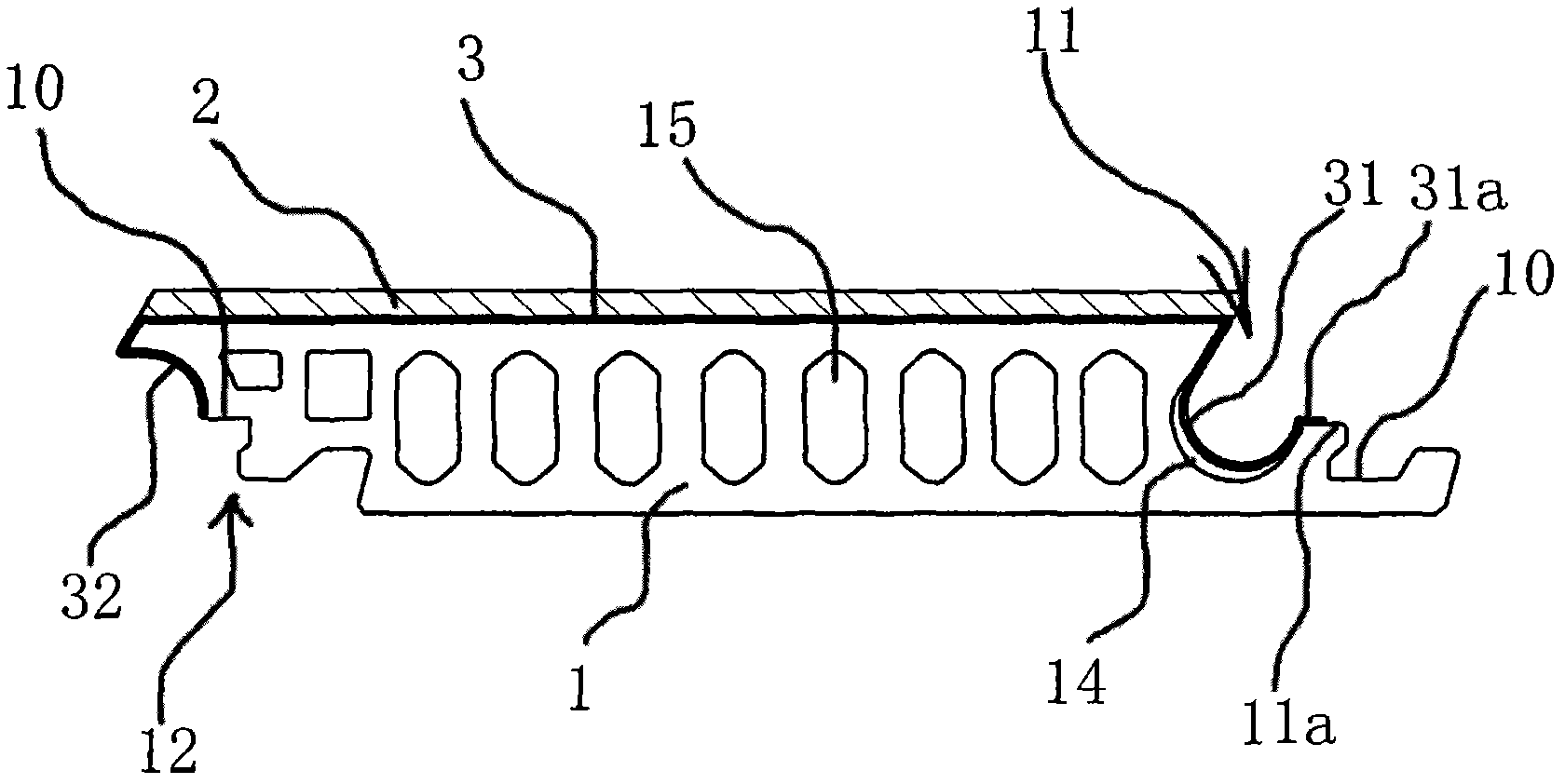
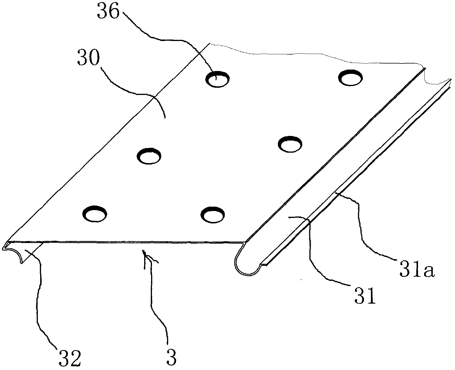
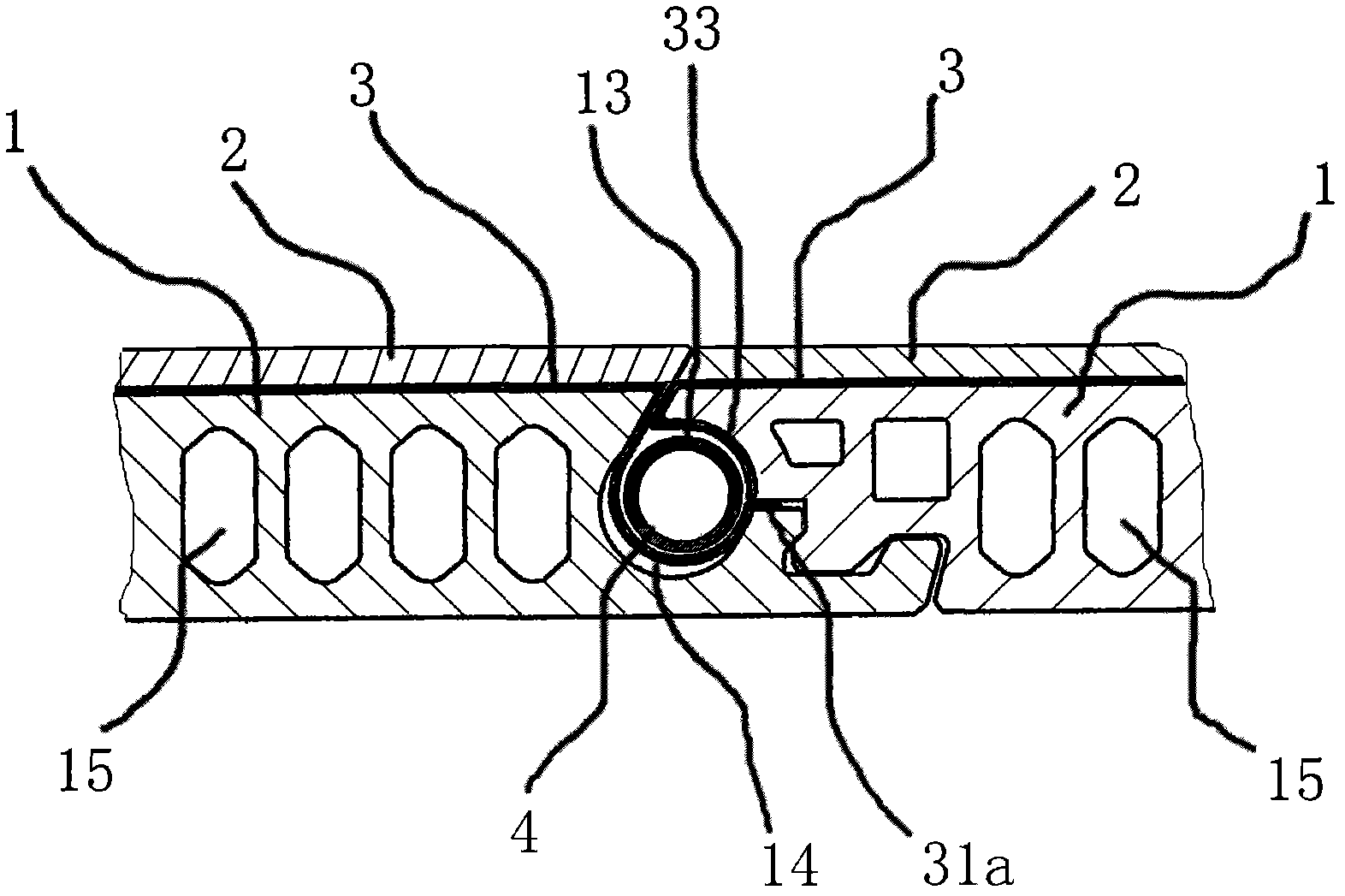
[0030] Such as figure 1 and 3 As shown, the local heating floor includes a base plate 1, a first connection structure 11 is provided on one side of the base plate 1, and a second connection structure 12 is provided on the other side. The first connection structure 11 and the second connection structure 12 respectively have concave-convex joint portions 10 . The first connecting structure 11 on one substrate 1 and the second connecting structure 12 on another adjacent substrate 1 can be snapped together, and when the first connecting structure 11 and the second connecting structure 12 are snapped together, they can form a longitudinal Extended accommodating cavity 13 . A decorative surface plate 2 is compounded on the front of the substrate 1 , and a heat-conducting medium layer 3 made of a heat-conducting material is provided between the substrate 1 and the decorative surface plate 2 . The heating element 4 extending longitudinally can be accommodated in the accommodating c...

Embodiment 2

[0035] Such as Figure 4 and 5 As shown, in this embodiment, the side of the heat conducting part 30 facing the substrate 1 has a longitudinally extending duct 34 , and the substrate 1 is provided with a longitudinally extending groove 16 for placing the duct 34 . The pipeline 34 is located on the center line of the heat conducting part 30 , and another heating body 4 is installed in the pipeline 34 . The rest are similar to those in Example 1, and will not be described in detail.

Embodiment 3

[0037] Such as Figure 6 As shown, in this embodiment, the heat conduction part 30 is composed of a first sheet-shaped body 301 and a second sheet-shaped body 302 which are arranged separately. The joint seam of the first sheet body 301 and the second sheet body 302 is located on the center line of the heat conducting part 30 . The rest are similar to those in Example 1, and will not be described in detail.


PUM


Abstract

The invention discloses a floorboard for floor heating. A first connecting structure is arranged at one side of a substrate, a second connecting structure is arranged at the other side of the substrate, the first connecting structure on one substrate can be mutually buckled with the second connecting structure on the other adjacent substrate, and when one first connecting structure and one second connecting structure are buckled, an accommodating cavity extending longitudinally can be formed; the front of each substrate is provided with a decorative surfacing board in a compounding way, a heat-conducting medium layer is arranged between each substrate and the corresponding decorative surfacing board, each heat-conducting medium layer comprises a heat-conducting part arranged on the front of the substrate as well as a first heated part and a second heated part, wherein the first heated part and the second heated part are arranged at two sides of the heat-conducting part and are respectively located on the first connecting structure and the second connecting structure; and when each first connecting structure and the corresponding second connecting structure are buckled, the first heated part and the second heated part are spliced to form a heating member accommodating cavity which is located inside the accommodating cavity and extends longitudinally, and a heating member is arranged in the heating member accommodating cavity and can transmit heat to the first heated part and the second heated part during heating.

Description

technical field [0001] The invention belongs to the technical field of decoration and decoration materials, and relates to floors, in particular to a geothermal floor. Background technique [0002] In the prior art, the heat conduction medium or heating element of the geothermal floor is set separately from the floor, or laid on the ground or installed inside other components such as the bottom plate between the ground and the floor. For example, Chinese patent literature discloses a composite geothermal floor [application number: CN 200510040599.2], which solves the problems of low thermal conductivity, large deformation and easy cracking of the surface of the existing geothermal floor. It includes a surface plate, a sub-surface plate, a core plate, and a bottom plate. A horizontal heat conduction groove is arranged in the core plate, and a longitudinal heat conduction groove is arranged in the bottom plate. Filled with heat transfer medium. In the above technical solutio...

Claims


Application Information

Patent Timeline
Patent Type & Authority Applications(China)
IPC IPC(8): E04F15/02F24D13/00F24D13/02
Inventor 李增清李渊
Owner 上海暖捷环境科技有限公司
Why Eureka
Try Eureka