
Portable photoelectric autocollimator based on area array CCD image sensor and working method of portable photoelectric autocollimator

A photoelectric autocollimator and image sensor technology, applied in the field of measuring instruments, can solve problems such as inability to reflect, aiming errors, and large measurement systems, and achieve the effects of improving measurement efficiency, simple operation and use, and reducing volume

Inactive Publication Date: 2011-09-07
UNIV OF SHANGHAI FOR SCI & TECH
View PDF3 Cites 18 Cited by
  • Summary
  • Abstract
  • Description
  • Claims
  • Application Information

AI Technical Summary

Problems solved by technology

There are artificial aiming errors and estimation errors in traditional mechanical autocollimators; linear array CCDs are used as photoelectric conversion devices in photoelectric autocollimators, which cannot reflect the angular displacement of the measured object in the two-dimensional direction, even if two lines The array CCD is placed vertically to realize the angular displacement measurement in the two-dimensional direction, but it is necessary to ensure that the two columns of CCDs are absolutely vertical, and there are also uncertainties; The system is too bulky and poor in portability

Method used


Image

  • Portable photoelectric autocollimator based on area array CCD image sensor and working method of portable photoelectric autocollimator
  • Portable photoelectric autocollimator based on area array CCD image sensor and working method of portable photoelectric autocollimator
  • Portable photoelectric autocollimator based on area array CCD image sensor and working method of portable photoelectric autocollimator

Examples


Embodiment Construction

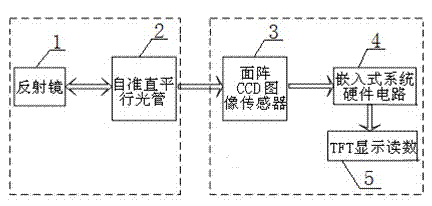
[0022] Such as figure 1 Shown is a block diagram of a portable photoelectric autocollimator based on an area array CCD image sensor. The system includes two parts: optical system and hardware circuit system.

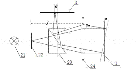
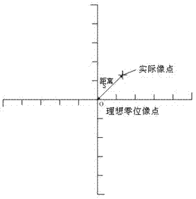
[0023] The optical system is composed of a self-collimating collimator 2 and a mirror 1. The basic measurement principle of the optical system is that the light emitted by an illuminated target located on the focal plane at the back of the collimator lens is projected to infinity after passing through the lens, and is reflected back after encountering the reflector, and then focused by the lens to form an image. If the reflector is perpendicular to the optical axis, the light will return to the original path after reflection, and the image will still fall on the ideal standard point; if the reflector is not perpendicular to the optical axis, the original parallel light will form an angle with the original light after being reflected by the reflector. After being focuse...


PUM


Abstract

The invention relates to a portable photoelectric autocollimator based on an area array CCD image sensor and a working method of portable photoelectric autocollimator. The autocollimator comprises an optical system and a hardware circuit system, wherein the optical system consists of a reflector and auto-collimation parallel light tubes, and the hardware circuit system consists of an area array CCD image sensor, an embedded system hardware circuit and real-time display liquid crystal; and after the area array CCD image sensor receives the image of the optical system, the data of the output image are transmitted to the embedded system hardware circuit through an acquisition channel and stored and processed, and finally, the calculated angular displacement information and the acquired image are displayed on the small area liquid crystal of the autocollimator in real time. The structure of the system is simplified and the volume of the system is reduced by adopting an embedded kernel chip, the screen displays the measurement results in real time, the measurement efficiency is improved, the operation and the use are simpler through a visual human-computer interface, and digitalization, two dimensions and portability of the photoelectric autocollimator are really realized.

Description

technical field [0001] The invention relates to a measuring instrument, in particular to a portable photoelectric autocollimator based on an area array CCD image sensor. Background technique [0002] Autocollimators currently on the market include mechanical autocollimators and photoelectric autocollimators. There are artificial aiming errors and estimation errors in traditional mechanical autocollimators; linear array CCDs are used as photoelectric conversion devices in photoelectric autocollimators, which cannot reflect the angular displacement of the measured object in the two-dimensional direction, even if two lines The array CCD is placed vertically to realize the angular displacement measurement in the two-dimensional direction, but it is necessary to ensure that the two columns of CCDs are absolutely vertical, and there are also uncertainties; The system is too bulky and poor in portability. Contents of the invention [0003] The present invention aims at the prob...

Claims


Application Information

Patent Timeline
IPC IPC(8): G01B11/26
Inventor 瑚琦杨园园高鹏飞郑遂
Owner UNIV OF SHANGHAI FOR SCI & TECH
Learn More