Shielded type connector

A connector and shielding technology, applied in the field of shielded connectors, can solve the problems of low processing efficiency of shielded connectors, and achieve the effect of improving processing efficiency

Active Publication Date: 2011-09-07
DEYI PRECISION ELECTRONIC IND CO LTD PANYU
View PDF4 Cites 8 Cited by
  • Summary
  • Abstract
  • Description
  • Claims
  • Application Information

AI Technical Summary

Problems solved by technology

[0006] In summary, the disadvantage of the existing shielded connectors is that the processing efficiency of the shielded connectors is relatively low

Method used


Image

  • Shielded type connector
  • Shielded type connector
  • Shielded type connector

Examples


Embodiment Construction

[0023] The shielded connector of the present invention will be further described below in conjunction with the accompanying drawings and specific embodiments.

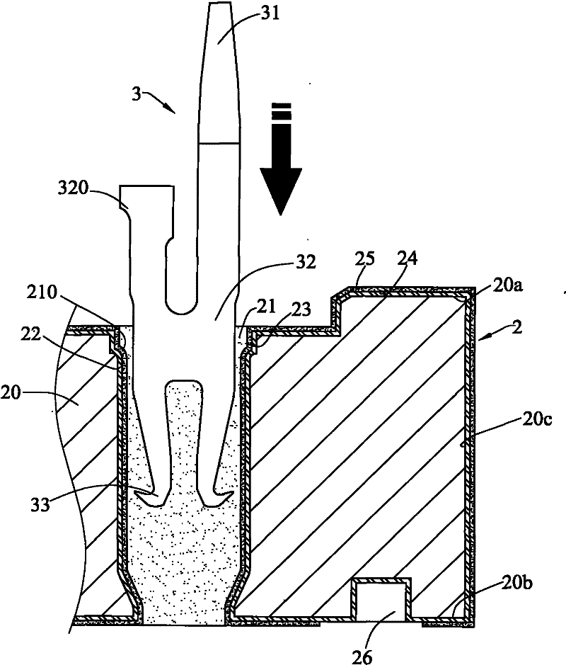
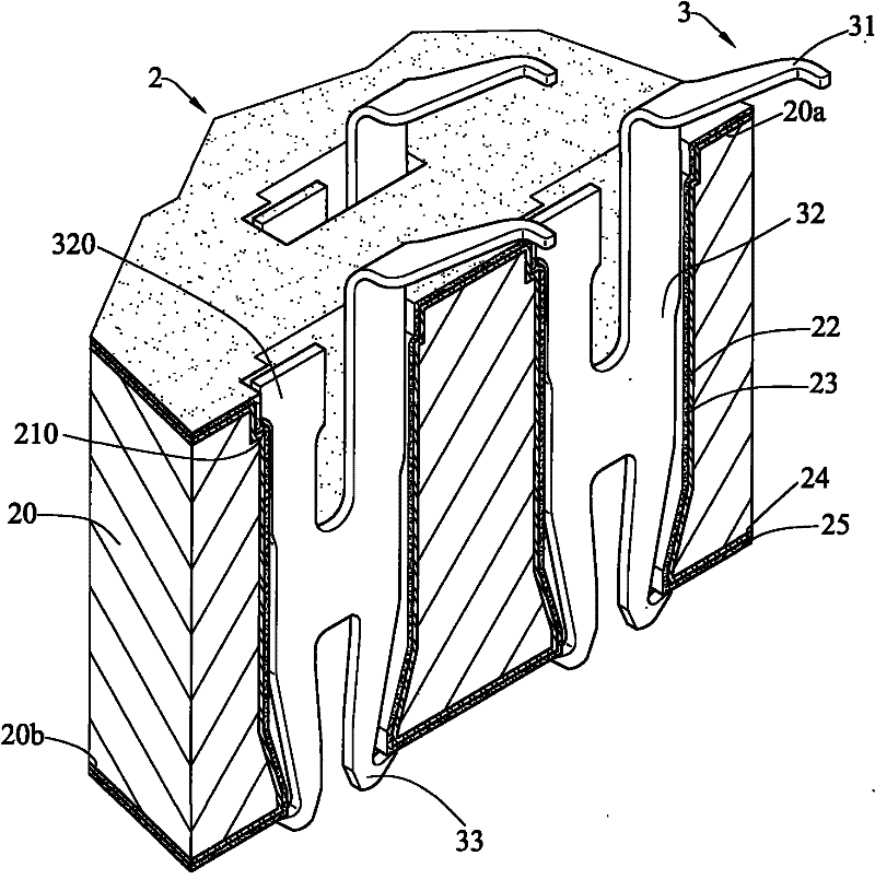
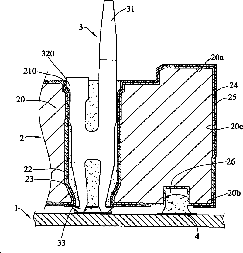
[0024] see figure 1 and figure 2 The shielded connector of the present invention connects a mating electronic component (not shown) to a motherboard 1 , and includes a base 2 in which a plurality of conductive terminals 3 are accommodated.

[0025] The base 2 includes an insulating body 20, which has an upper surface 20a and a lower surface 20b oppositely arranged, the upper surface 20a is adjacent to the docking electronic component, the lower surface 20b is adjacent to the motherboard 1, and is connected to A plurality of side surfaces 20c of the upper surface 20a and the lower surface 20b.

[0026] The insulating body 20 also includes a plurality of receiving grooves 21 passing through the upper surface 20a and the lower surface 20b, a shielding body 22 is provided on the inner surface of each of the receiving gr...


PUM


Abstract

The invention provides a shielded type connector which comprises a base, wherein the base is provided with a plurality of accommodating slots; shields are formed in physical coating mode on the internal surfaces of at least part of accommodating slots; an insulated paint layer is formed on each shield in the way of dipping or spraying or coating; at least a conductive connector is arranged outside the accommodating slot and is connected with the shields, at least one export part is arranged adjacent to a mother board, and the conductive connector is electrically connected to the mother board by the export part; a plurality of conductive terminals are accommodated in the accommodating slots; each conductive terminal comprises a contact part exposed at one side of the base, a main body partextending into a corresponding accommodating slot from the contact part, and a connection part extending into and exposed at the accommodating slot from the main body part. As the insulated paint layer can be formed on the base in the way of dipping or spraying or coating, the formation efficiency can be improved; meanwhile, the thickness of the insulated paint layer is small, which does not influence the size of the accommodating slots and does not increase the assembling difficulty of the conductive terminals.

Description

【Technical field】 [0001] The invention relates to a shielded connector, in particular to a shielded connector which can improve processing efficiency. 【Background technique】 [0002] In order to solve the problem of electromagnetic interference in the signal transmission process, a shielded connector is designed, which electrically connects a pair of electronic components to a motherboard, including a base and a plurality of conductive terminals accommodated in the base . [0003] The base includes a plurality of storage tanks, each of which is provided with a shielding body on the inner surface of the storage tank, and an insulating block with a through hole is also installed in each of the storage tanks, and a conductor is located in the storage tank. outside the slot, and the conductor is located on the bottom surface of the base, the conductor is connected to each of the shields, and a plurality of lead-out parts are arranged adjacent to the motherboard, and the lead-ou...

Claims


Application Information

Patent Timeline
Patent Type & Authority Applications(China)
IPC IPC(8): H01R13/02H01R13/40H01R13/46H01R13/6588H01R13/6591H01R12/51H01R43/00
CPCH01R13/24H01R13/6582H01R13/035H01R12/714H01R13/6599Y10T29/49002
Inventor 朱德祥
Owner DEYI PRECISION ELECTRONIC IND CO LTD PANYU
Why Eureka
Try Eureka