High-power optical burn-in

A light-aging, high-power technology, applied in optics, light guides, lasers, etc., can solve problems such as inability to properly screen out lasers, unreliable structures, etc.

Inactive Publication Date: 2011-09-07
FINISAR
View PDF5 Cites 3 Cited by
  • Summary
  • Abstract
  • Description
  • Claims
  • Application Information

AI Technical Summary

Problems solved by technology

Clearly, however, conventional TBI may not be able to properly screen out lasers made of other materials such as indium aluminum gallium arsenide (“InAlGaAs”), which may have inherently less reliable structures

Method used


Image

  • High-power optical burn-in
  • High-power optical burn-in
  • High-power optical burn-in

Examples


Embodiment Construction

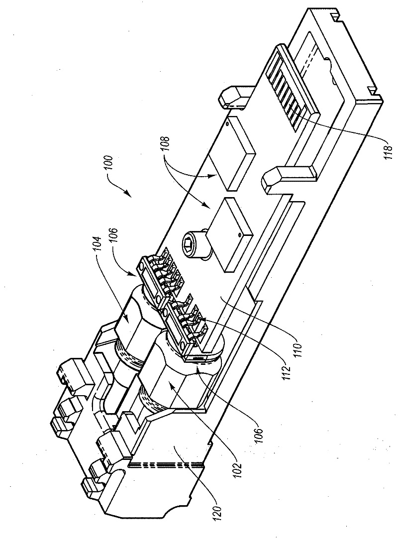
[0019] Embodiments of the present invention relate to methods and systems for testing optoelectronic devices such as, but not limited to, laser diodes. The methods and systems of the present invention provide identification of defective and / or unreliable laser diodes that cannot be identified by conventional TBI methods. In contrast to traditional TBI burn-in, embodiments of the present invention include operating at relatively large drive currents (such as three to four times the normal operating bias current at elevated temperatures) and relatively low temperatures, such as room temperature Device aging treatment. Embodiments of the present invention may help to identify problematic optoelectronic devices to improve the reliability of the devices ultimately sold to the laser manufacturer / seller's customers.

[0020] Reference will now be made to the drawings, wherein like structures will be designated with like reference numerals. It is to be understood that the drawings a...


PUM


Abstract

Semiconductor lasers are aged to identify weak or flawed devices, resulting in improved reliability of the remaining devices. The lasers can be aged using a high-power optical burn-in that includes providing a high drive current to the lasers for a period of time, and maintaining the ambient temperature of the lasers at a low temperature. After the high-power optical burn-in, the output of the lasers can be measured to determine if the lasers are operating within specifications. Those that are not can be discarded, while those that are can be further aged using a high-temperature thermal burn-in that includes providing a drive current to the lasers while maintaining the ambient temperature of the lasers at a high-temperature.

Description

technical field [0001] The present invention generally relates to testing of semiconductor lasers. More specifically, embodiments of the present invention relate to high power photoaging. Background technique [0002] Aging processes are commonly utilized in the production of optical components such as laser diodes. Due to inconsistencies in manufacturing techniques and materials, optical components may have actual life cycles that differ significantly from design or theoretical life cycles. The industry standard is to operate optical components in a manufacturing facility for an extended period of time, and those optical components whose lifetime is shorter than ideal are expected to fail during initial operation. Therefore, these failed optical components do not leave the manufacturing plant to impede the flow of data in the optical network. [0003] In the case of conventional laser diode manufacturing, aging of the laser diode involves operating the laser diode for an...

Claims


Application Information

Patent Timeline
Patent Type & Authority Applications(China)
IPC IPC(8): H01S5/00H01S3/0941
CPCH01S5/0021H01S5/22G01R31/2849H01S5/02248G02B6/4246H01S5/02325
Inventor 须藤剑罗伯特·W·赫里克查尔斯·B·罗斯洛T·H·奥拉·舍隆德
Owner FINISAR
Why Eureka
Try Eureka