
Method for machining side punch through hole of mold punching device

A technology of side-punching punches and processing methods, which is applied in the field of punch through-hole processing, and can solve problems such as long programming time, low processing efficiency, and high cost

Inactive Publication Date: 2011-09-14
SHANDONG WEIFANG FOTON MOLD
View PDF6 Cites 1 Cited by
  • Summary
  • Abstract
  • Description
  • Claims
  • Application Information

AI Technical Summary

Problems solved by technology

The current processing method for machining the elongated hole is: use a milling cutter to directly mill out an elongated hole, but because there is no bottom hole, it must be processed by layer cutting, which has low processing efficiency, high cost, and long programming time

Method used


Image

  • Method for machining side punch through hole of mold punching device
  • Method for machining side punch through hole of mold punching device
  • Method for machining side punch through hole of mold punching device

Examples


Embodiment Construction

[0019] Below in conjunction with accompanying drawing and embodiment, further elaborate the present invention. In the following detailed description, certain exemplary embodiments of the invention are described by way of illustration only. Needless to say, those skilled in the art would realize that the described embodiments can be modified in various different ways, all without departing from the spirit and scope of the present invention. Accordingly, the drawings and description are illustrative in nature and not intended to limit the scope of the claims.

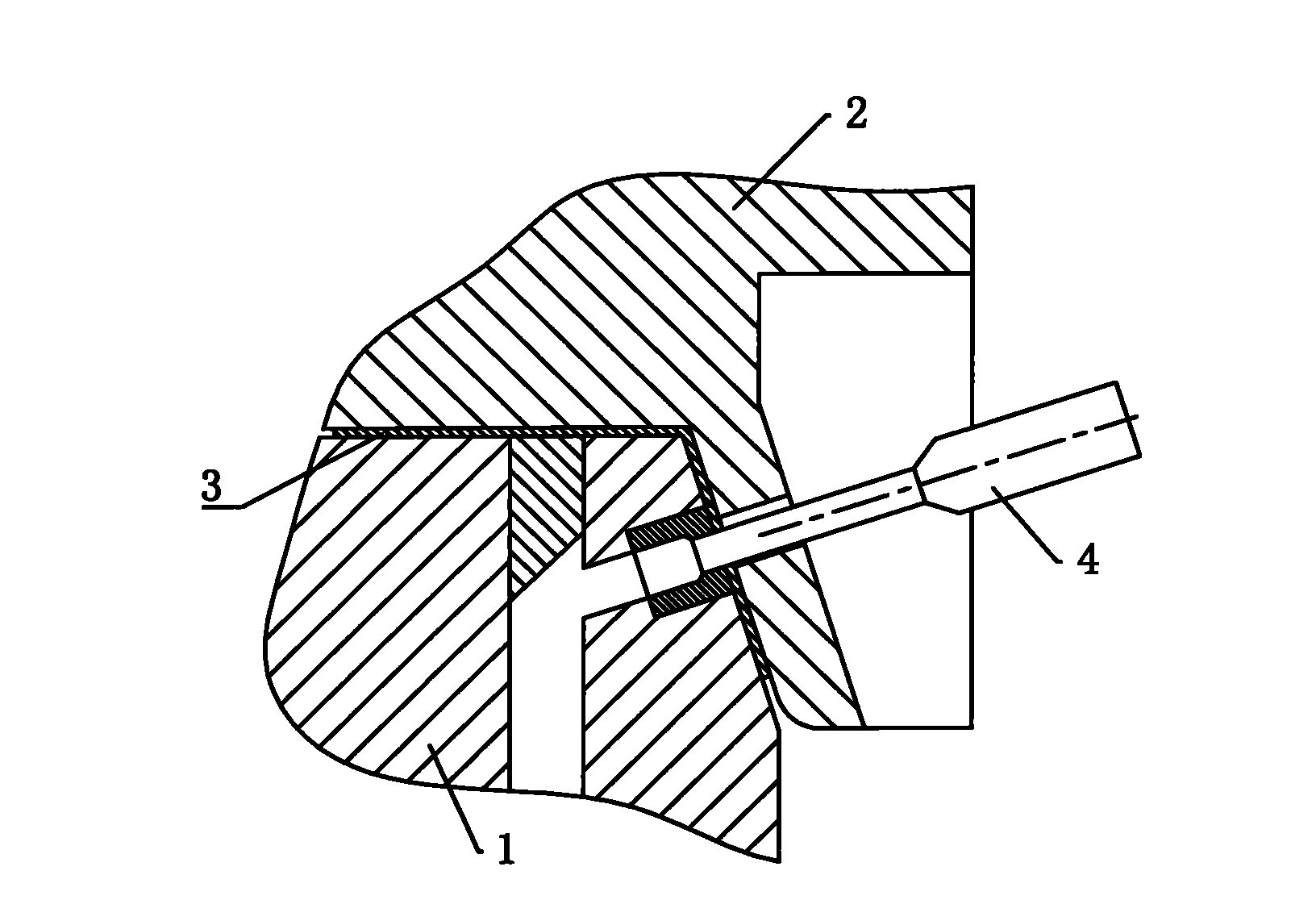
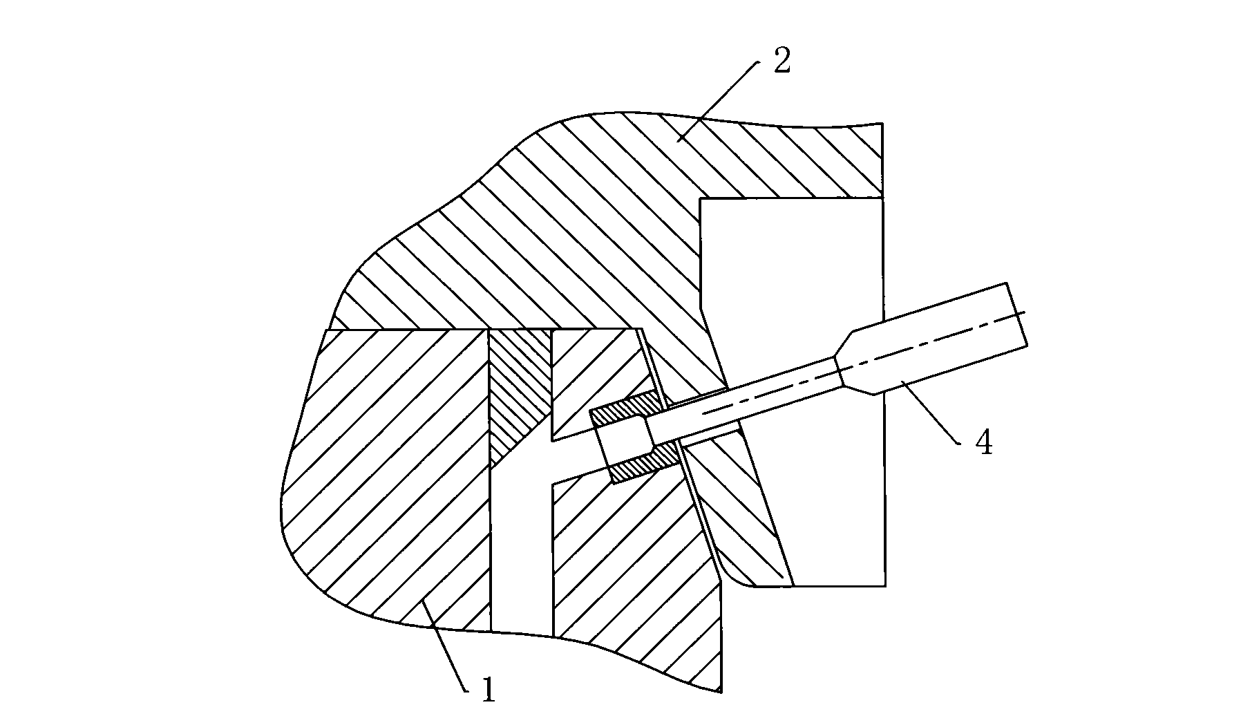
[0020] Such as figure 1 and figure 2 As shown, comparing the situation when the tablet 3 is placed between the lower die 1 and the presser 2 and when the tablet 3 is not placed, in both cases, the lower die 1 has a certain displacement relative to the presser 2, If the size of the through hole of the presser is adapted to the situation of putting the tablet 3, it is not suitable for the situation when the tablet 3 is ...


PUM


Abstract

The invention discloses a method for machining a side punch through hole of a mold punching device, which comprises the following steps: 1, when sheets are not fed, adhering the lower bottom surface of a punching device to the upper surface of a lower mold, and determining a through hole positioning circle for the idle motion of a side punch through hole on the side wall of the punching device according to a side punch hole corresponding to the lower mold; 2, when the sheets are fed, determining a through hole positioning circle for the punching motion of the side punch through hole on the side wall of the punching device according to the side punch hole corresponding to the lower mold; 3, drawing an enveloping circle enveloping the through hole positioning circle for the idle motion and the through hole positioning circle for the punching motion on the side wall of the punching device; and 4, drilling the side punch through hole along the enveloping circle, wherein the diameter of the side punch through hole is greater than that of the enveloping circle. In the method, on the premise of ensuring the punching function of the mold, a milling process method which must be used originally is changed into a drilling method, and the advantages such as multiple sizes of drill bits, high cutting efficiency and convenient sharpening process are fully taken, thereby achieving the purpose of enhancing the machining efficiency and reducing the cost.

Description

technical field [0001] The invention relates to a punch through hole processing method, in particular to a side punch through hole processing method. Background technique [0002] At present, when changing molds in domestic stamping factories, lubricating oil is first applied to the moving parts of the mold, and the moving parts of the mold are moved several times, and then the blank stamping parts are placed. The mold with side punching content is required to be able to move freely with and without the material sheet, and there should not be too much gap. Because if the gap is too large, the presser cannot play a good role in pressing the material during punching, and the punching edge is easy to curl, but if the gap is too small, the side punch may interfere and break when working. [0003] Usually, in order to offset the difference between the mold with and without material, the through hole of the press is designed as a long round hole to achieve the purpose. The curre...

Claims


Application Information

Patent Timeline
IPC IPC(8): B23B35/00
Inventor 刘会平王存第李树新
Owner SHANDONG WEIFANG FOTON MOLD
Learn More