Substrate positioning method suitable for screen printing technology

A technology of screen printing and positioning method, applied in screen printing machine, printing, printing machine and other directions, can solve the problems of camera mechanical error, long printing cycle, etc., to avoid mechanical error, short printing cycle and high accuracy Effect

Inactive Publication Date: 2011-09-14
ZHEJIANG UNIV
View PDF6 Cites 27 Cited by
  • Summary
  • Abstract
  • Description
  • Claims
  • Application Information

AI Technical Summary

Problems solved by technology

[0004] The purpose of this invention is to provide a substrate positioning technology suitable for screen printing technology in view of the problems of long printing cycle and mechanical error in camera installation in current screen printing technology

Method used


Image

  • Substrate positioning method suitable for screen printing technology
  • Substrate positioning method suitable for screen printing technology
  • Substrate positioning method suitable for screen printing technology

Examples


Embodiment Construction

[0027] The present invention will be further described below in conjunction with the accompanying drawings and examples.

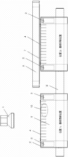
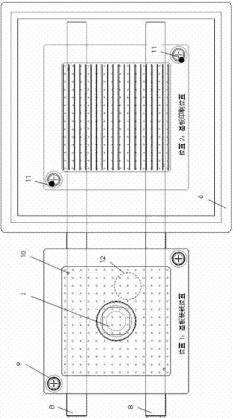
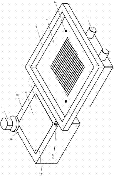
[0028] combine figure 1 , figure 2 , image 3 , Figure 4 As shown, a substrate positioning technology suitable for screen printing technology, including:

[0029] 1) The present invention has an upper visual optical device 1 , a lower visual optical device 3 and a movable printing table 5 . In this technology, PCB, wafer, silicon wafer or other forms of printed substrates are loaded on the substrate loading position, and the substrate 4 is fixed on the surface of the printing table 5 by means of vacuum adsorption and fixation 12 .

[0030] 2) After the substrate 4 is fixed, the upper vision optical device 1 is used to scan the substrate 4 and the printing table 5, and when the reference mark 10 of the substrate and the reference mark 9 on the surface of the printing table are observed at the same time, the reference mark of the substrate is recorded ...


PUM


Abstract

The invention discloses a substrate positioning method suitable for a screen printing technology, which comprises the following steps of: adsorbing a substrate on the surface of a printing worktable; scanning by using an upper visual optical device to obtain the relative position of a reference mark of the substrate and a reference mark on the surface of the printing worktable; moving the substrate with the printing worktable until the substrate is below a printing screen frame, and scanning by using a lower visual optical device to obtain the relative position of the reference mark on the surface of the printing worktable and a reference mark of a screen; performing coordinate conversion to obtain a relative position relationship of the reference mark of the substrate and the reference mark of the screen because the reference mark on the surface of the printing worktable is scanned in two-time scanning, and performing fine adjustment on the screen frame; and printing when the substrate and the screen are completely aligned. The method is suitable for screen printing on a surface mount technology production line, electrode screen printing on a solar cell production line, and a similar production process for coating the surface of the substrate by using a scraper on the basis that the screen and the substrate are accurately aligned.

Description

technical field [0001] The invention relates to screen printing technology, in particular to a substrate positioning method suitable for screen printing technology. Background technique [0002] Screen printing technology (Screen Printing) is more and more widely used in the field of surface mount technology (SMT) and solar cell electrode printing technology (Solar Metallization). In the traditional screen printing technology, the positioning of the substrate and the screen is often through a visual optical device that can be observed up and down at the same time, observing two or more pairs of fiducial marks on the screen and the substrate, and using relative coordinates to achieve positioning; In this technology, visual optical devices often have two degrees of freedom of movement in XY directions. Scan a pair of fiducial marks, and then move the camera out) Scan two or more pairs of fiducial marks on the substrate or printing table and screen, and then perform relative p...

Claims


Application Information

Patent Timeline
Patent Type & Authority Applications(China)
IPC IPC(8): B41F15/20
Inventor 刘宝庆范坤泉陈宽先钱路燕
Owner ZHEJIANG UNIV
Why Eureka
Try Eureka