Clamping device for piecing and connecting pouring template of building

A clamping device and formwork technology, which is applied to the joints of formwork/formwork/work frame, the preparation of building components on site, and construction, etc., which can solve the uneven surface of the building body, high labor intensity of workers, and increased labor costs. and other problems, to achieve the effect of reduced labor intensity, simple structure, and reduced technical requirements for installation

Inactive Publication Date: 2012-10-03
阮中亮
View PDF0 Cites 0 Cited by
  • Summary
  • Abstract
  • Description
  • Claims
  • Application Information

AI Technical Summary

Problems solved by technology

Since the bolts need to be inserted into the holes one by one and tightened, the work efficiency is low and the labor intensity of the workers is high; especially when connecting and fixing the pouring formwork on the bottom surface, the workers have to raise their heads and raise their hands for a long time to operate , the labor intensity is greater, the neck and arms will be sore after a long time, and long-term labor often leads to spine and upper limb diseases
In addition, in order to facilitate the bolts to pass through the connection holes of the formwork frame, the gap between the bolts and the holes is relatively large. During the process of tightening the bolts, due to the influence of the twisting action, the originally aligned formwork often appears misplaced, resulting in pouring out. The surface of the building is uneven, which affects the pouring quality
In order to ensure the installation quality of the pouring formwork, highly skilled workers are required for installation. Since the highly skilled workers need to pay higher wages, this leads to an increase in labor costs.

Method used


Image

  • Clamping device for piecing and connecting pouring template of building
  • Clamping device for piecing and connecting pouring template of building
  • Clamping device for piecing and connecting pouring template of building

Examples


Embodiment Construction

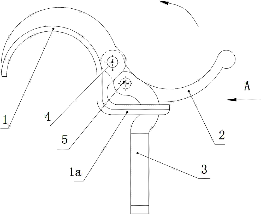
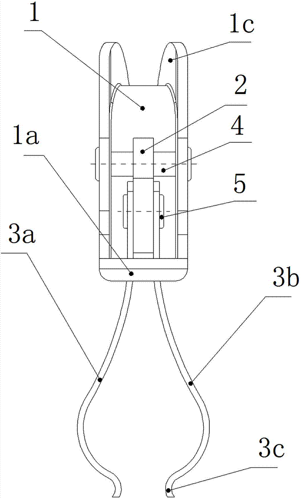
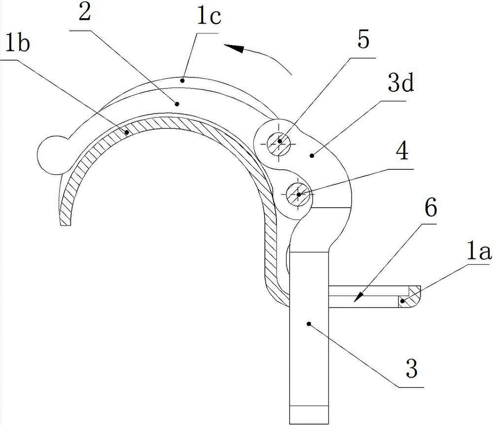
[0033] See Figure 1 to Figure 9 , An embodiment of the clamping device for the splicing and connection of the building pouring formwork includes a bracket 1, a movable handle 2, an elastic clamp 3 made of spring steel with left and right clamping parts. The bracket 1 has a hook portion 1b and a horizontal extension portion 1a that is turned from one end of the hook portion. The horizontal extension portion 1a is provided with a rectangular hole 6 for restraining the elastic clip. The hook portion 1b of the bracket 1 is provided with a round The circular arc groove 1d of the tube buckling, the circular arc groove 1d is set as a semi-circular groove, so that it can grasp the circular tube on the support frame of the construction casting template to form a positioning; of course, the hook part of the bracket can also be provided with The rectangular groove 1e used to buckle with the square tube, so that it can hold the square tube on the support frame of the construction casting ...


PUM


Abstract

The invention relates to a clamping device for piecing and connecting a pouring template of a building. The clamping device comprises a support, a moving handle and an elastic clip, wherein the elastic clip is made of spring steel, and is provided with a left and a right clamping parts; the support is provided with a hooking part, and a horizontal extending part used for restraining a rectangularhole of the elastic clip is arranged on the support; the moving handle is hinged with the support by taking the end part at one end of the moving handle as a fulcrum and the other end of the moving handle as a force point, and a gravity point is arranged between the fulcrum and the force point, and is hinged with the upper end of the elastic clip; the elastic clip penetrates through the rectangular hole of the support, and freedom for the displacement of the elastic clip is preserved in the longitudinal direction of the rectangular hole; the lower parts of the left and the right clamping parts of the elastic clip are of an inward opposite bent shape; when in a free state, the lower parts of the left and the right clamping parts open, and the opening distance of the lower parts is greater than the width of the rectangular hole of the support; and the upper parts of the left and the right clamping parts make contact with the long edges of the rectangular hole. The clamping device can beused for rapidly fastening and connecting the pieced pouring template, and has the advantages of convenience for use, simple structure and easiness for manufacture.

Description

Technical field [0001] The invention relates to the field of fastening devices, and in particular to a clamping device for splicing and connecting building pouring templates. Background technique [0002] When concrete pouring columns, beams, walls, and floor floors are used in construction projects, several building pouring templates are used to form a pouring mold, and the concrete is poured into the pouring mold to form. At present, the fasteners used to split, connect and fix the building pouring formwork are usually bolts. The bolts are manually inserted through the holes provided on the pouring formwork, and then the bolts are tightened to form a fastening. Because the bolts need to be inserted into the holes and tightened one by one, the work efficiency is low, and the labor intensity of the workers is high; especially when connecting and fixing the pouring template located on the bottom surface, the workers must raise their heads and raise their hands for a long time to o...

Claims


Application Information

Patent Timeline
Patent Type & Authority Patents(China)
IPC IPC(8): E04G17/00E04G13/02E04G13/04
Inventor 阮中亮
Owner 阮中亮
Why Eureka
Try Eureka