
High-pressure bidirectional miniature power-driven air pump

An electric air pump and micro technology, applied in the direction of pumps, piston pumps, machines/engines, etc., can solve the problems of limited capacity, large volume and large volume of high-pressure gas cylinders, and achieve good starting performance under pressure, simple and simplified transmission mechanism. The effect of transmission

Active Publication Date: 2011-09-14
BEIJING CONST INSTR TECH INC
View PDF6 Cites 18 Cited by
  • Summary
  • Abstract
  • Description
  • Claims
  • Application Information

AI Technical Summary

Problems solved by technology

The manual air pump is mainly used in the manual pressure instrument verification device. In order to complete the normal verification process, the operator needs to continuously operate the manual air pump to ensure that there is enough compressed air during the verification process. This is a heavy physical work, which seriously affects the quality of the verification work. Efficiency, with the improvement of industrial automation, automatic verification devices for gas pressure instruments have appeared, using high-pressure gas cylinders to provide compressed air for the verification devices. changes, and it is impossible to meet the needs of automatic calibration of pressure instruments on the industrial site. In order to solve this problem, people envisage replacing high-pressure gas cylinders with electric air pumps. , poor start-up performance under pressure, etc., cannot meet the needs of small flow and high pressure in this industry, all of which seriously restrict the development of automatic, miniaturized, and highly integrated gas pressure instrument automatic verification devices

Method used


Image

  • High-pressure bidirectional miniature power-driven air pump
  • High-pressure bidirectional miniature power-driven air pump
  • High-pressure bidirectional miniature power-driven air pump

Examples


Embodiment Construction

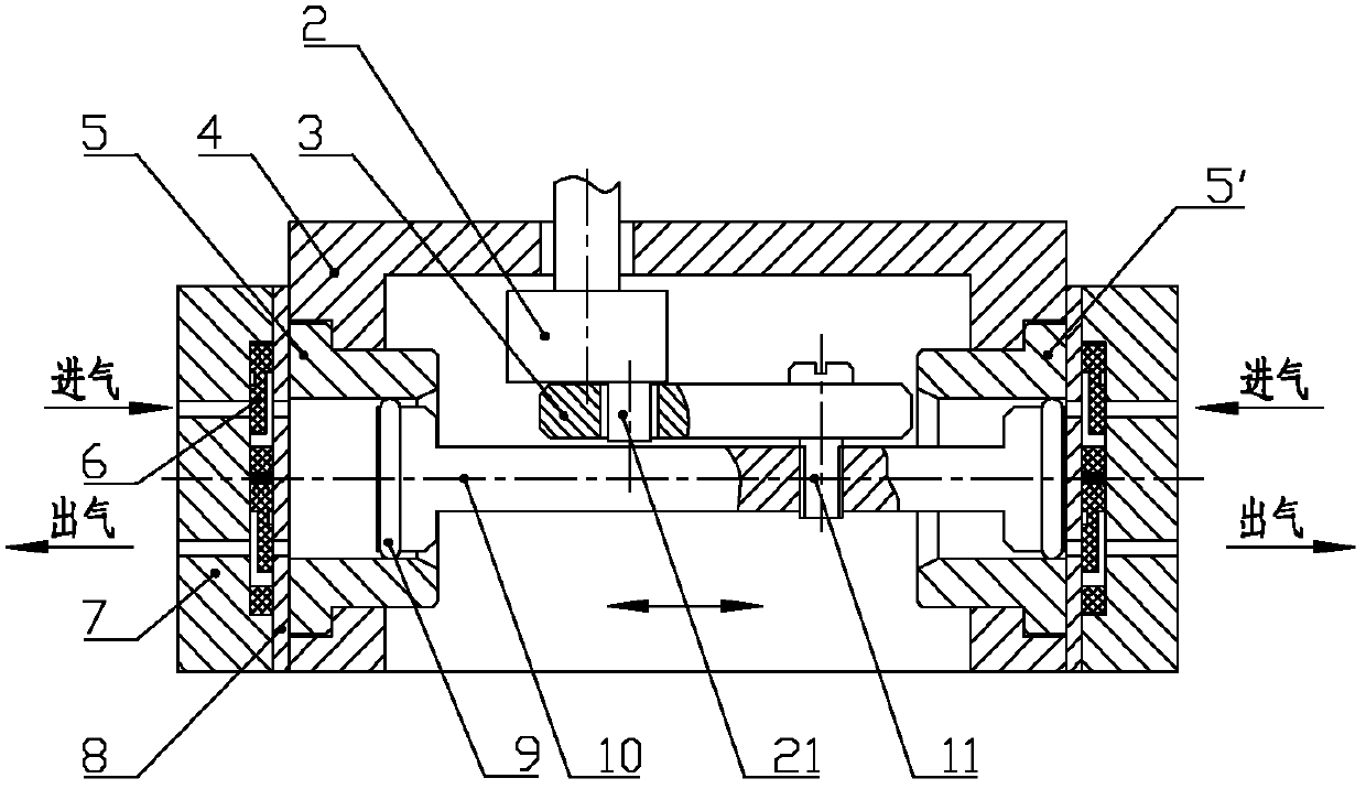
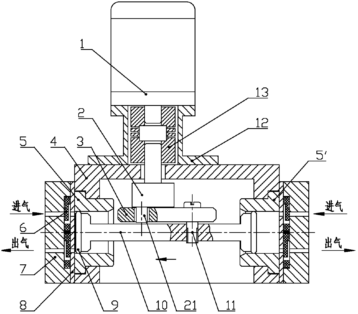
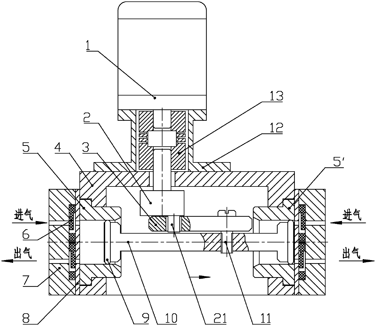
[0014] For the specific structure of the high-pressure bidirectional miniature electric air pump of the present invention, see Figure 1-Figure 3 shown, where figure 1 The main components are shown; figure 2 It shows the limit working position of the left piston in the compression state and the right piston in the suction state; image 3 It shows the limit working position where the right piston is in the compression state and the left piston is in the suction state.

[0015] see Figure 1-Figure 3 , the high-pressure two-way miniature electric air pump of the present invention includes a motor 1, an eccentric shaft 2, a swing rod 3, a pump body 4, a left cylinder body 5 and a right cylinder body 5', a one-way valve body 6, a cylinder head 7, a cylinder Pad 8, sealing ring 9, piston rod 10 and screw 11, motor bracket 12, coupling 13. in:

[0016] Pump body 4 is the connection part of this electric air pump, and motor 1 is fixed on the pump body 4 by motor support 12, and...


PUM


Abstract

The invention discloses a high-pressure bidirectional miniature power-driven air pump which comprises a motor, an eccentric shaft, an oscillating bar, a pump body, a left cylinder body, a right cylinder body, a piston rod, and a one-way valve body and a cylinder cover connected with the two cylinder bodies, wherein the motor is fixed on the pump body, a motor shaft is connected with the eccentricshaft, a driving pin at one end of the eccentric shaft penetrates through one installation hole of the oscillating rod, the oscillating rod is connected on the piston rod arranged horizontally by a screw, sealing rings are arranged on two ends of the piston rod and stretch into the left and the right cylinder bodies respectively, and the two cylinder bodies are respectively arranged at two ends of the pump body. The power-driven air pump has the advantages of small volume, light weight, low power consumption, capacity of generating high pressure, wide pressure range, good starting performancewith pressure, and the like, and can satisfy the requirements of the industry on small flow and high pressure.

Description

technical field [0001] The invention belongs to the technical field of pressure instrument standards, and in particular relates to a standard electric air pump that can generate gas pressure and is used for pressure instruments. Background technique [0002] In the verification process of gas pressure instruments, compressed air with a certain pressure is required as the medium to verify the instruments. There are two main sources of compressed air in the traditional way: manual air pumps and high-pressure cylinders. The manual air pump is mainly used in the manual pressure instrument verification device. In order to complete the normal verification process, the operator needs to continuously operate the manual air pump to ensure that there is enough compressed air during the verification process. This is a heavy physical work, which seriously affects the quality of the verification work. Efficiency. With the improvement of industrial automation, automatic verification devi...

Claims


Application Information

Patent Timeline
Patent Type & Authority Applications(China)
IPC IPC(8): F04B35/04
Inventor 姜维利
Owner BEIJING CONST INSTR TECH INC
Learn More