Non-contact laser detecting instrument for displaying roughness of steel ball

A non-contact, detector technology, applied in the field of measurement, can solve the problems of high loss of laser light source, difficult movement, large space occupation, etc., to achieve the effect of increasing effective photosensitive ability, high moving accuracy, and convenient adjustment

Inactive Publication Date: 2011-09-14
LUOYANG BEARING SCI & TECH CO LTD
View PDF1 Cites 9 Cited by
  • Summary
  • Abstract
  • Description
  • Claims
  • Application Information

AI Technical Summary

Problems solved by technology

[0004] 1. Both the steel ball adjustment device and the swing adjustment device adopt a worm gear structure, which takes up a large space, high cost, bloated structure, and relatively loud noise;
[0005] 2. The laser tube is exposed on the outside, and the loss of the laser light source is large, which affects the effective light sensing of the photoelectric sensor. The adjustment structure is too simple, difficult to adjust, and affects the appearance of the entire detection device;
[0006] 3. The limit device is just a simple swing rod, which cannot be adjusted in height, and the gap is large, s

Method used


Image

  • Non-contact laser detecting instrument for displaying roughness of steel ball
  • Non-contact laser detecting instrument for displaying roughness of steel ball
  • Non-contact laser detecting instrument for displaying roughness of steel ball

Examples


Embodiment Construction

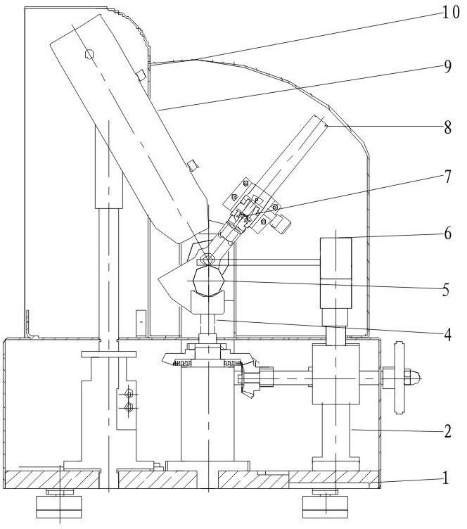
[0033] The detector of the present invention adopts the principle of laser speckle in the measurement principle. The key to the mechanical structure of the detector is to adjust the incident light spot of the laser tube, the top of the steel ball and the center of rotation of the sensor adjustment device to one point, that is, the three points are on the same line. , at the same time, the reflected light spot just falls on the very center of the optical nuclear sensor, and the entire optical path is well protected by a dark room. In this case, the error can be minimized and the measurement standard can be met.

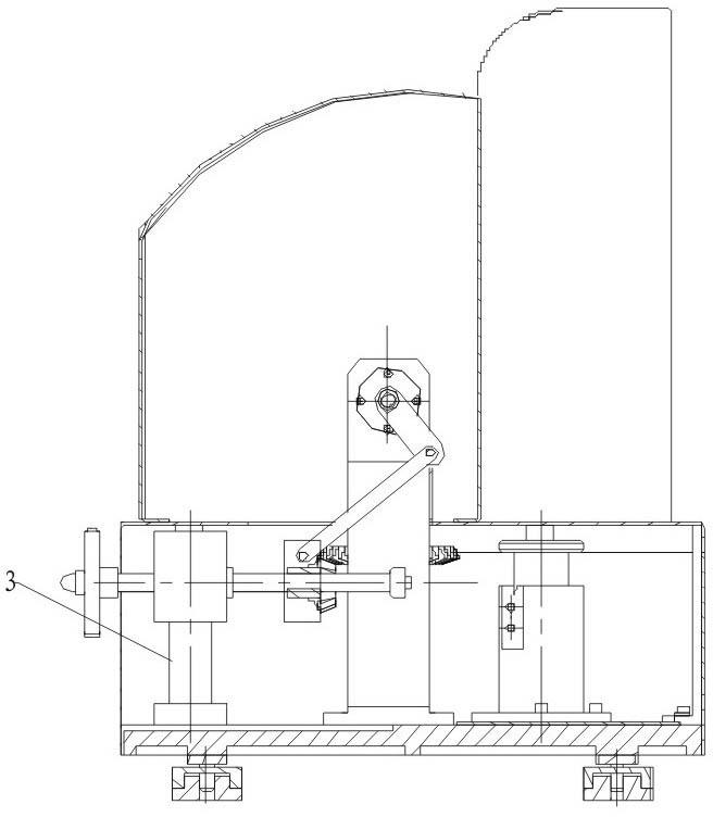
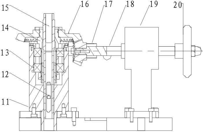
[0034] Such as figure 1 , 2Shown: steel ball adjustment device (2), swing adjustment device (3), laser tube and adjustment device (9) are fixed on the base (1), steel ball adjustment device (2) is fixed in the middle of the base (1), measure The mandrel (4) is installed on the lifting shaft (15) in the steel ball adjustment device (2), and the measured steel ball (5) ...


PUM


Abstract

The invention relates to a non-contact laser detecting instrument for displaying the roughness of a steel ball, which comprises a base (1), a steel ball adjusting device (2), a swing adjusting device (3), a measuring mandrel (4), a limiting device (6), a photoelectric sensor (7), a swing receiving device (8), a laser tube, a laser tube adjusting device (9) and a shell (10). In the non-contact laser detecting instrument provided by the invention, a laser speckle principle is adopted on a measuring principle; the mechanical structure of the detecting instrument has the key points that the incidence speckle of the laser tube, the top end of the steel ball and the gyration center of the sensor adjusting device are adjusted to one point, i.e. three points are on the same line; simultaneously, the reflected speckles are right positioned in the right center of a photonuclear sensor; and the whole light path is in a good darkroom protection mode, and errors are reduced to the minimum under the condition that the whole light path is in the good darkroom protection mode, thereby reaching measurement standards. The non-contact laser detecting instrument provided by the invention has the advantages of high measuring speed, no damage to the measured steel ball (5), simplified structure of the detecting instrument, cost reduction, appearance improvement, simple and convenient operation and strong detection reliability.

Description

[0001] technical field [0002] The invention belongs to the technical field of measurement, and in particular relates to a non-contact laser detector for displaying the roughness of steel balls. Background technique [0003] The steel ball roughness meters currently on the market have the following defects in the mechanical mechanism: [0004] 1. Both the steel ball adjustment device and the swing adjustment device adopt a worm gear structure, which takes up a large space, high cost, bloated structure, and relatively loud noise; [0005] 2. The laser tube is exposed on the outside, and the loss of the laser light source is large, which affects the effective light sensing of the photoelectric sensor. The adjustment structure is too simple, difficult to adjust, and affects the appearance of the entire detection device; [0006] 3. The limit device is just a simple swing rod, which cannot be adjusted in height, and the gap is large, so it cannot really play the role of limi...

Claims


Application Information

Patent Timeline
IPC IPC(8): G01B11/30
Inventor 宋晓波朱孔敏单连新张慧熊子健姜力
Owner LUOYANG BEARING SCI & TECH CO LTD
Why Eureka
Try Eureka