Milling machine

A milling machine and sliding table technology, applied in milling machine equipment, milling machine equipment details, large fixed members, etc., can solve the problems of slow cutting speed, low work efficiency, low finish, etc., to improve machining accuracy, high machining efficiency, and high finish. Effect

Active Publication Date: 2014-11-05
TAIAN XINJIE MACHINERY
View PDF7 Cites 9 Cited by
  • Summary
  • Abstract
  • Description
  • Claims
  • Application Information

AI Technical Summary

Problems solved by technology

[0002] At present, when machining the stepped structure on the insulating pad, milling cutters are usually used for cutting. However, because the milling cutter is limited by the amount of cutting each time, the cutting speed is slow and the work efficiency is low. At the same time, the milling cutter cuts out The stepped surface is relatively rough and the finish is low

Method used


Image

  • Milling machine

Examples


Embodiment Construction

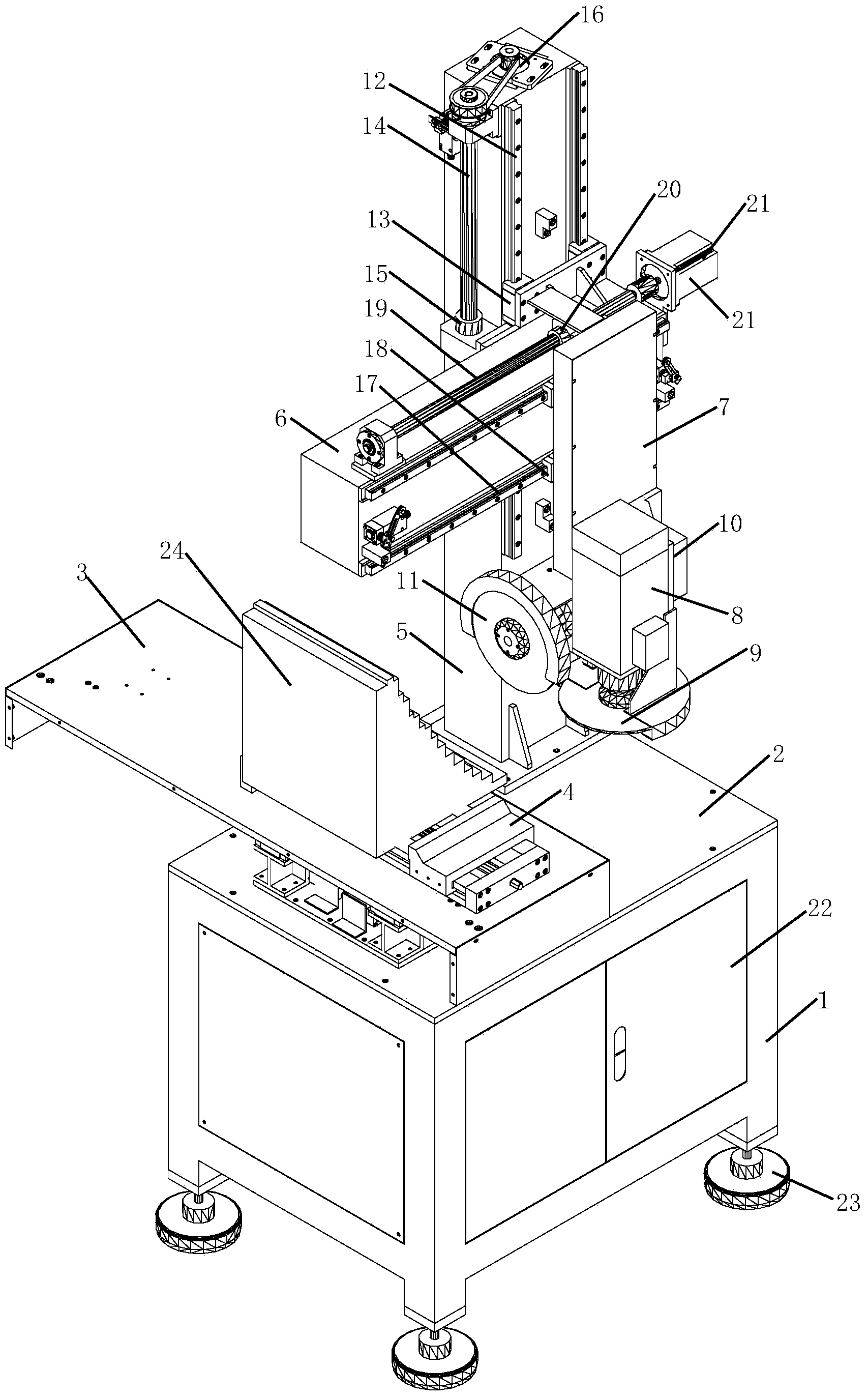
[0017] Such as figure 1 As shown, the milling machine of the present invention includes a base 1, a workbench 2 is arranged above the base 1, and a Y-axis slide table 3 movable along the Y-axis is provided on the left side of the workbench 2, and the Y-axis A pad clamping device 4 is provided on the slide table 3, a Z-axis support 5 is fixed on the workbench 3, and an X-axis slide table 6 capable of moving up and down along the Z-axis is provided on the inner surface of the Z-axis support 5 , the inner surface of the X-axis slide table 6 is provided with a Z-axis slide table 7 that can move along the X-axis, and the bottom of the Z-axis slide table 7 is provided with a first high-speed motor 8, driven by the first high-speed motor 8 Horizontal saw blade 9, the second high-speed motor 10 and the vertical saw blade 11 driven by the second high-speed motor 10; the plane where the vertical saw blade 11 is located is parallel to the Y axis; the Z-axis pillar 5 and the X-axis slide ...


PUM


Abstract

The invention discloses a milling machine. The milling machine comprises a pedestal; a workbench is arranged above the pedestal; the left side of the workbench is provided with a Y-axis sliding table capable of sliding along a Y-axis; a cushion block clamping device is mounted on the Y-axis sliding table; a Z-axis pillar is fixed on the workbench; the inner side surface of the Z-axis pillar is provided with an X-axis sliding table capable of sliding up and down along a Z-axis; the inner side surface of the X-axis sliding table is provided with a Z-axis sliding table capable of sliding along an X-axis; and the bottom of the Z-axis sliding table is provided with a first high-speed motor, a horizontal saw blade driven by the first high-speed motor, a second high-speed motor and a vertical saw blade driven by the second high-speed motor. The invention has the following beneficial effects: (1), the milling machine has a simple structure; (2) machining efficiency is high, the surface of a sawed step-like structure is smooth and free of burrs and has high fineness; (3) processing precision is improved; (4) the whole milling machine can be conveniently adjusted to be horizontal; and (5) control precision is high, and cost is low.

Description

technical field [0001] The invention relates to a machine tool, especially a milling machine. Background technique [0002] At present, when machining the stepped structure on the insulating pad, milling cutters are usually used for cutting. However, because the milling cutter is limited by the amount of cutting each time, the cutting speed is slow and the work efficiency is low. At the same time, the milling cutter cuts out The stepped surface is relatively rough and the finish is low. Contents of the invention [0003] The problem to be solved by the present invention is to provide a milling machine with simple structure, high work efficiency and high surface finish. [0004] In order to solve the above problems, the milling machine of the present invention includes a base, a workbench is arranged above the base, and a Y-axis slide table that can move along the Y-axis is provided on the left side of the workbench. A pad clamping device is provided, and a Z-axis pillar ...

Claims


Application Information

Patent Timeline
Patent Type & Authority Applications(China)
IPC IPC(8): B23C9/00B23P23/02B23Q5/40B23Q1/01
Inventor 付全刚乔秀海
Owner TAIAN XINJIE MACHINERY
Why Eureka
Try Eureka