
Template transmission mechanism for template-transporting sewing machine

A transmission mechanism and sewing machine technology, which is applied to sewing machine components, sewing machine control devices, sewing equipment, etc., can solve the problems of slow template transmission speed, slippage between rollers and templates, and low production efficiency, so as to provide sewing quality, stable transmission, The effect of high processing efficiency

Active Publication Date: 2013-11-20
ZHEJIANG ZOJE SEWING MACHINE
View PDF5 Cites 11 Cited by
  • Summary
  • Abstract
  • Description
  • Claims
  • Application Information

AI Technical Summary

Problems solved by technology

[0004] For the automatic mold-moving sewing machine of this structure, after the template is placed on the processing position on the workbench, the template is driven by the friction of the roller with knurling. Since the template needs to move back and forth when the mold-moving sewing machine is processing, the rollers Rolling friction is easy to slip, once the roller slips, the sewing effect will be poor; the greater the rotation speed of the roller, the greater the possibility of slipping between the roller and the template, the speed of the roller is limited, the transmission speed of the template is limited, and the transmission speed of the template slower, less productive

Method used


Image

  • Template transmission mechanism for template-transporting sewing machine
  • Template transmission mechanism for template-transporting sewing machine
  • Template transmission mechanism for template-transporting sewing machine

Examples


Embodiment Construction

[0022] The following are specific embodiments of the present invention in conjunction with the accompanying drawings to further describe the technical solutions of the present invention, but the present invention is not limited to these embodiments.

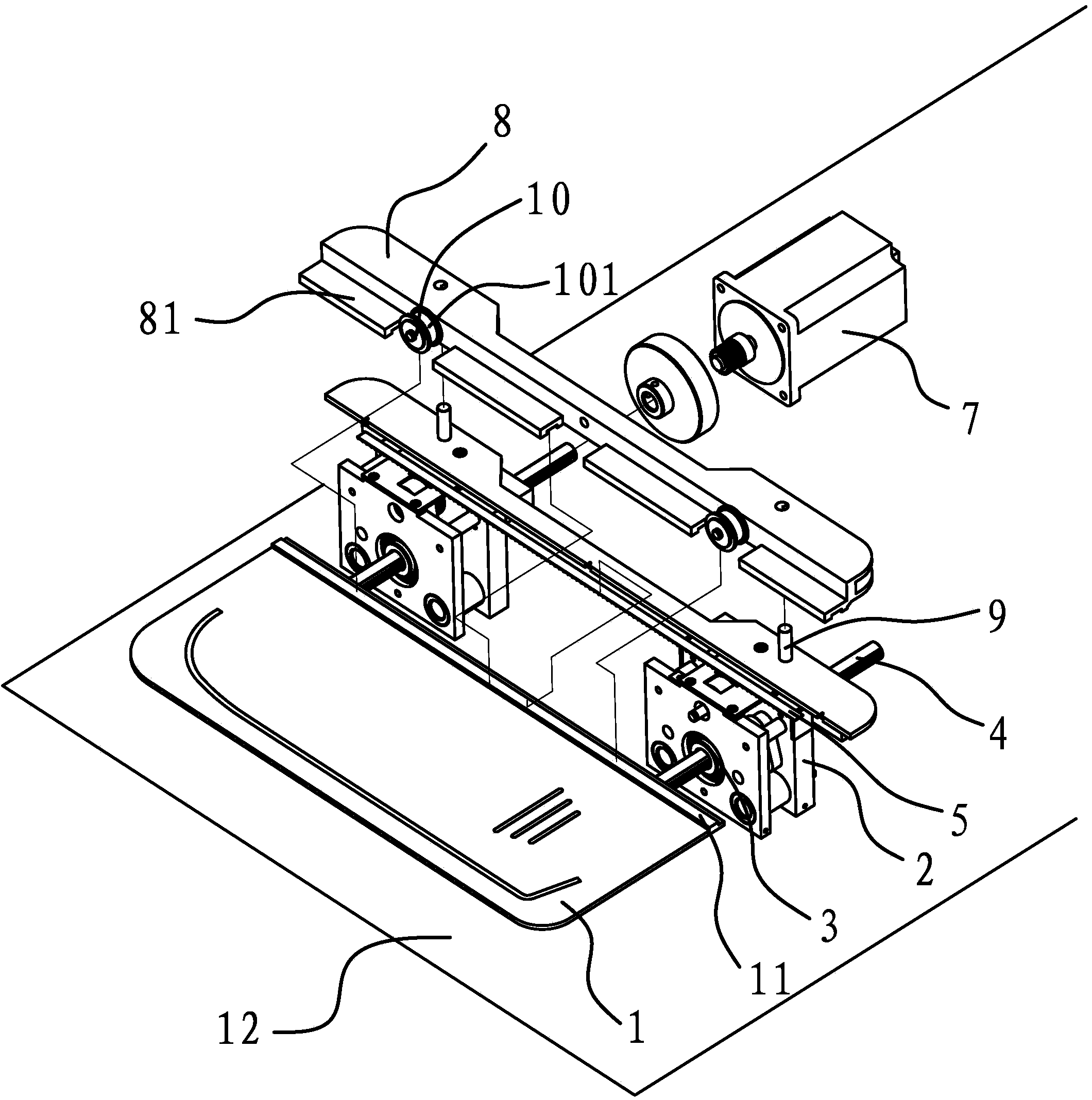
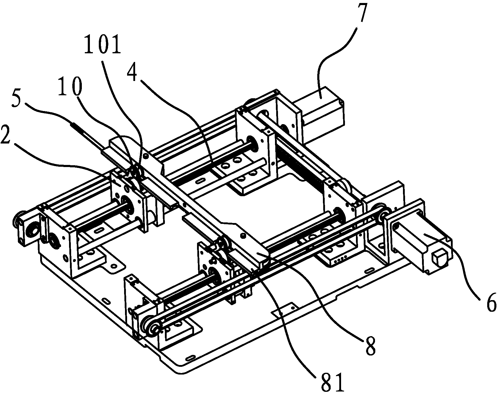
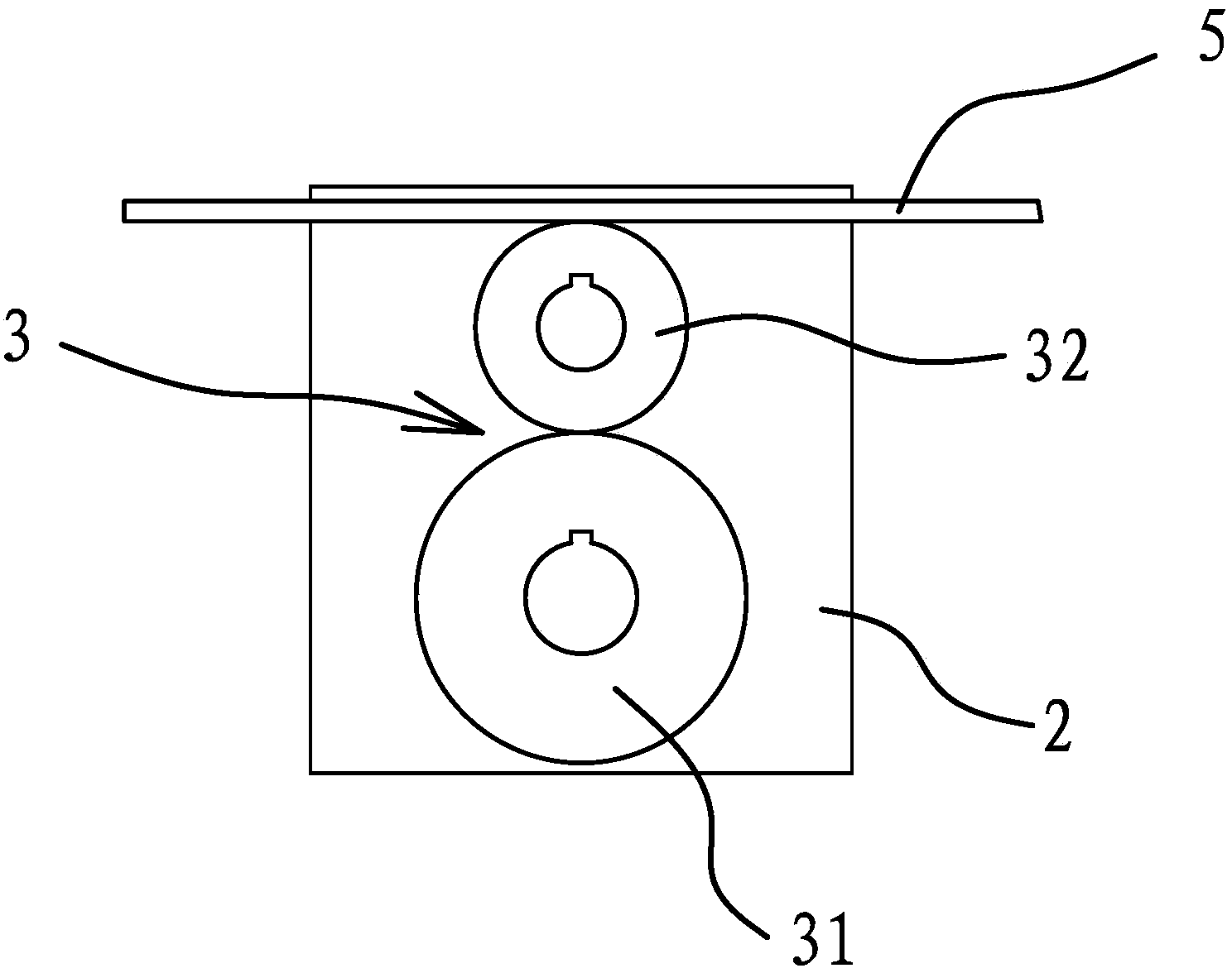
[0023] Such as figure 1 , figure 2 As shown, the transmission mechanism of the template 1 of the present model sewing machine includes a transmission base 2, a transmission gear 3, a transmission shaft 4, a rack 5, a driving member 6 and a driving member 7.

[0024] The template 1 is designed according to the garment parts to be processed. The lower part of the template 1 is fixedly connected with a rack 5, and the upper part of the template 1 is provided with a guide bar 11. The rack 5 and the guide bar 11 are arranged opposite to each other, and the rack 5 is located on the back of the template 1 , The guide bar 11 is located on the front side of the template 1. The template 1 is located at the workbench 12, and the driving part 6 ...


PUM


Abstract

The invention provides a template transmission mechanism for a template-transporting sewing machine, belongs to the technical field of sewing machine manufacturing, and solves the problems of low template transmission speed, low production efficiency and the like of the conventional template transmission mechanism for the template-transporting sewing machine. The template of the template transmission mechanism for the template-transporting sewing machine is positioned at a worktable. The mechanism comprises a transmission seat, a transmission gear, a transmission shaft, a gear rack, a first drive piece and a second drive piece; the transmission gear is positioned in the transmission seat; both the first drive piece and the second drive piece are fixedly connected with the worktable; the first drive piece is connected with the transmission seat and can drive the transmission seat to move frontward and backward; the second drive piece is connected with one end of the transmission shaft; the other end of the transmission shaft is positioned in the transmission seat and is connected with the transmission gear; the gear rack is fixedly connected with the lower part of the template and is engaged with the transmission gear; and the template can translate leftward and rightward when the transmission gear drives the gear rack to translate. The template transmission mechanism for the template-transporting sewing machine has the advantages of high transmission stability, high transmission speed, high machining efficiency and the like.

Description

Technical field [0001] The invention belongs to the technical field of sewing machine manufacturing, and relates to a model transport sewing machine, in particular to a template transmission mechanism of the model transport sewing machine. Background technique [0002] The pattern sewing machine designs sewing templates according to the craftsmanship of various parts of the clothing, and then places the sewing templates on the sewing machine to automatically and efficiently complete the sewing in accordance with the technological standards. It is widely used in the current garment production. Through the use of sewing templates and the reasonable arrangement of the assembly line, garment factories can reduce their dependence on skilled workers, solve technical bottlenecks, improve sewing efficiency, ensure uniform quality of sewing products, and provide positive assistance for batch and standardized operations. [0003] The template clamping transmission mechanism of the automatic ...

Claims


Application Information

Patent Timeline
Patent Type & Authority Applications(China)
IPC IPC(8): D05B69/08D05B69/30D05B35/00
Inventor 李家银杨培孙灵君
Owner ZHEJIANG ZOJE SEWING MACHINE
Learn More