System for detecting solder joint reliability of circuit board by using infrared multipoint temperature measuring heat resistance method

A detection system and circuit board technology, which is applied in the field of detection systems, can solve problems such as normal appearance and unrecognizable virtual solder joints, and achieve good development prospects and high reliability of detection results

Active Publication Date: 2011-09-14
HARBIN INST OF TECH
View PDF3 Cites 29 Cited by
  • Summary
  • Abstract
  • Description
  • Claims
  • Application Information

AI Technical Summary

Problems solved by technology

[0009] The purpose of the present invention is to solve the problem that the existing detection technology cannot identify the virtual solder joints with normal appearance and electrical connection, and to provide a detection system that uses infrared multi-point temperature measurement and thermal resistance method to detect the reliability of circuit board solder joints

Method used


Image

  • System for detecting solder joint reliability of circuit board by using infrared multipoint temperature measuring heat resistance method
  • System for detecting solder joint reliability of circuit board by using infrared multipoint temperature measuring heat resistance method
  • System for detecting solder joint reliability of circuit board by using infrared multipoint temperature measuring heat resistance method

Examples


specific Embodiment approach 1

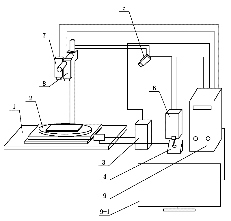
[0025] Specific implementation mode one: the following combination figure 1 To describe this embodiment,

[0026] This embodiment includes a system platform 1, an XY rotary stage 2, a stage drive controller 3, an infrared laser 5, a laser controller 6, an optical microscope camera 7, an infrared thermal imager 8 and a computer 9,

[0027] The XY rotary stage 2 is set on the system platform 1,

[0028] The optical microscopic camera 7 and the infrared thermal imager 8 are located directly above the XY rotary stage 2, and the infrared laser 5 is positioned above the side of the XY rotary stage 2. The optical microscopic camera 7, the thermal infrared imager 8 and the infrared laser 5 are all fixed on the support of the system platform 1,

[0029] The displacement signal output end of the stage drive controller 3 is connected to the displacement signal input end of the XY rotary stage 2,

[0030] The control signal input end of the infrared laser 5 is connected to the control ...

specific Embodiment approach 2

[0036] Specific implementation mode two: the following combination figure 1 This embodiment is described. The difference between this embodiment and Embodiment 1 is that it also includes a stage manual controller 4, and the manual signal output end of the stage manual controller 4 is connected to the manual signal output terminal of the XY rotary stage 2. signal input. Others are the same as the first embodiment.

[0037] In this embodiment, the manual controller 4 is used to control the displacement of the XY rotary stage 2. The manual controller 4 can be used in conjunction with the stage driving controller 3, or can be used separately.

[0038] The manual controller 4 can adopt the driving mode of a manual stepping motor to meet the detection requirements.

specific Embodiment approach 3

[0039] Specific implementation mode three: the following combination figure 1 Describe this embodiment, the difference between this embodiment and Embodiment 1 or 2 is that the control signal input end of the stage drive controller 3 is connected to the stage drive signal output end of the computer 9; the control of the laser controller 6 The signal input end is connected to the laser control signal output end of the computer 9, and the signal processing result of the computer 9 is displayed through the display 9-1. Others are the same as the first or second embodiment.

[0040] In this embodiment, the computer 9 is used to comprehensively control the entire system, so that the overall system can be coordinated and coordinated, the positioning is more accurate, the precision is higher, and the automation of the detection system is realized.


PUM


Abstract

The invention relates to a system for detecting the solder joint reliability of a circuit board by using an infrared multipoint temperature measuring heat resistance method, which belongs to the technical field of cold solder joint detection and solving the problems that according to the conventional detection technology, cold solder joints which have normal appearance and are electrically connected can not be identified. An XY rotatable object stage is arranged on a system platform, an optical microscope camera and an infrared thermal imager are positioned above the XY rotatable object stage; an infrared laser is positioned at the side upper part of the XY rotatable object stage; a displacement signal output end of an object stage driving controller is connected with a displacement signal input end of the XY rotatable object stage; a control signal input end of an infrared laser is connected with a control signal output end of a laser controller; an image signal output end of the optical microscope camera is connected to an image signal input end of a computer; and a collection signal output end of the infrared thermal imager is connected with a thermal imager signal input end of the computer. The system is used for detecting the solder joint reliability of circuit boards.

Description

technical field [0001] The invention relates to a detection system for detecting the reliability of solder joints of circuit boards by adopting an infrared multi-point temperature measurement and thermal resistance method, and belongs to the technical field of solder joint virtual solder detection of printed circuit boards. Background technique [0002] Welding of solder joints is a common problem in the production process of printed circuit boards (PCB). Due to the complexity of the factors causing solder joints, it is impossible to completely remove them in the production process. Therefore, the detection of solder joints is very important. important. At present, the detection methods of virtual solder joints mainly include automatic optical inspection (AOI), automatic X-ray inspection (AXI) and flying probe test. [0003] The automatic optical inspection (AOI) method captures the mounting image on the surface of the circuit board component by the CCD camera, and then per...

Claims


Application Information

Patent Timeline
Patent Type & Authority Applications(China)
IPC IPC(8): G01N25/18
Inventor 孔令超田艳红王春青刘威安荣
Owner HARBIN INST OF TECH
Why Eureka
Try Eureka