Mode coupling light assembly

A mode coupling, optical component technology, applied in the field of optical communication, can solve the problems of optical power loss, optical signal weakening, and limitation of optical fiber links, and achieve the effect of increasing the optical power budget, increasing the transmission distance, and avoiding additional losses.

Active Publication Date: 2011-09-14
SHENZHEN HI OPTEL TECH +1
View PDF6 Cites 4 Cited by
  • Summary
  • Abstract
  • Description
  • Claims
  • Application Information

AI Technical Summary

Problems solved by technology

The optical power of the laser used for optical signal transmission at the ONU end is limited, which is +2-+7dBm, and the sensitivity of the photodetector used for optical signal reception by the OLT is also limited, which is -36--28dBm. When the signal is transmitted for a certain distance in the optical fiber o

Method used


Image

  • Mode coupling light assembly
  • Mode coupling light assembly
  • Mode coupling light assembly

Examples


Embodiment Construction

[0021] In order to make the object, technical solution and advantages of the present invention clearer, the present invention will be further described in detail below in conjunction with the accompanying drawings and embodiments. It should be understood that the specific embodiments described here are only used to explain the present invention, not to limit the present invention.

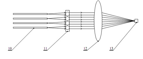
[0022] figure 2 The optical path principle of the mode-coupling optical component provided by the first embodiment of the present invention is shown, and the mode-coupling optical component includes a collimator array 11 , an aspheric lens 12 and a photodetector 13 . The collimator array 11 collimates the optical signals emitted from each optical fiber 10 into parallel light, and the aspheric lens 12 converges the collimated parallel light onto the photodetector 13 .

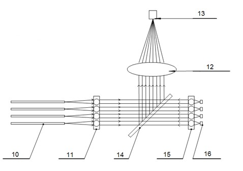
[0023] In this embodiment, the optical coupler and the light receiving component are packaged together. The specific implementat...


PUM


Abstract

The invention is applicable to the field of optical communication and provides a mode coupling light assembly. The assembly comprises a collimator array, an aspherical lens and a photoelectric detector, wherein the collimator array collimates an optical signal transmitted from each path of optical fiber into parallel light; and the aspherical lens converges the collimated parallel light to the photoelectric detector. The collimator array is needed to meet the requirement that the cross section of emergent beams is smaller than a clear aperture of the aspherical lens, and the converging angle is needed to accord with a numerical aperture of the photoelectric detector after the light is converged by the aspherical lens. In the embodiment of the invention, the mode coupling light assembly couples a plurality of paths of optical signals transmitted by fiber nodes to the photoelectric detector of an optical receiving assembly of optical cable terminal equipment in a low optical power penalty mode, additional loss brought by an optical coupler is avoided, and the optical power budget in an optical fiber transmission network is improved; therefore, the assembly contributes to improving the splitting ratio and increasing the transmission distance in a passive optical network.

Description

technical field [0001] The invention belongs to the field of optical communication, in particular to a mode coupling optical component. Background technique [0002] At present, the passive optical network (Passive Optical Network, PON) architecture used by FTTx is to transmit multi-routing optical nodes (Optical Network Unit, ONU) through the optical passive device-optical coupler (Coupler or PLC). The optical signal is coupled to an optical fiber for transmission, and then coupled to the optical cable terminal equipment (Optical Line Terminal, OLT), see figure 1 . [0003] The optical signal transmitted by the multi-routing ONU is coupled to one optical fiber through the optical passive device - the optical coupler. The optical power loss of the coupling is very serious, and the optical power loss of 4 channels is about 7dB, and the 8 channels are 1. The optical power of the path loss is about 10dB, and the relationship between the optical power loss PL and the number of...

Claims


Application Information

Patent Timeline
IPC IPC(8): G02B6/42
Inventor 郑启飞廖振兴
Owner SHENZHEN HI OPTEL TECH
Why Eureka
Try Eureka