
Integrated panel type grid drive circuit applicable for charge sharing pixel

A gate drive circuit and gate technology, applied in static memory, instruments, static indicators, etc., can solve the problems of complex circuit structure and large layout area of ​​shift register, and achieve the effect of simple circuit structure and simple circuit layout.

Active Publication Date: 2011-09-14
AU OPTRONICS CORP
View PDF5 Cites 32 Cited by
  • Summary
  • Abstract
  • Description
  • Claims
  • Application Information

AI Technical Summary

Problems solved by technology

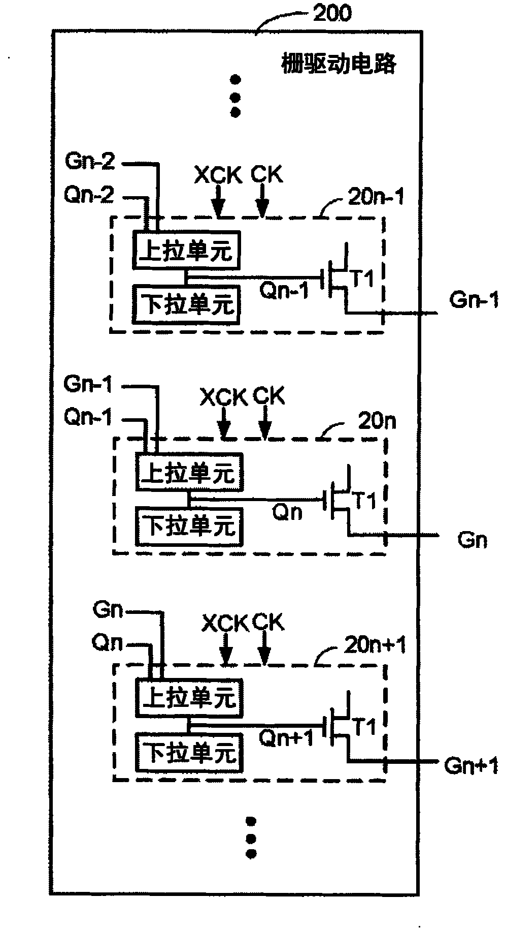
therefore Figure 4A In , the circuit structure of each shift register is more complex and occupies a larger layout area (layout area)

Method used


Image

  • Integrated panel type grid drive circuit applicable for charge sharing pixel
  • Integrated panel type grid drive circuit applicable for charge sharing pixel
  • Integrated panel type grid drive circuit applicable for charge sharing pixel

Examples


Embodiment Construction

[0066] According to an embodiment of the present invention, the present invention proposes an integrated panel-type gate driving circuit applied to a charge-sharing pixel. The gate drive circuit on the GOA panel includes a plurality of shift registers, and each shift register can output a main gate drive signal and a sub gate drive signal that do not overlap with each other.

[0067] First, the present invention needs to generate 6 clock pulse signals, all of which have a duty cycle of 1 / 3. Furthermore, the phase difference between each clock pulse signal is 60 degrees. The six clock pulse signals are named as HC1, HC2, HC3, HC4, HC5, HC6 according to the phase sequence. Such as Figure 5 Shown is the phase relationship between the six clock pulse signals.

[0068] Please refer to Figure 6A and Figure 6B , which is a schematic diagram of the first embodiment of the shift register in the gate driving circuit of the present invention and its related signals. The nth shif...


PUM


Abstract

The invention discloses an integrated panel type grid drive circuit applicable for charge sharing pixels. According to the invention, the grid drive circuit on a liquid crystal panel comprises a plurality of shift registers. Each of the shift registers can output non-overlapped main grid drive signals and sub-grid drive signals. Meanwhile, the integrated panel type grid drive circuit is simple in structure and circuit layout.

Description

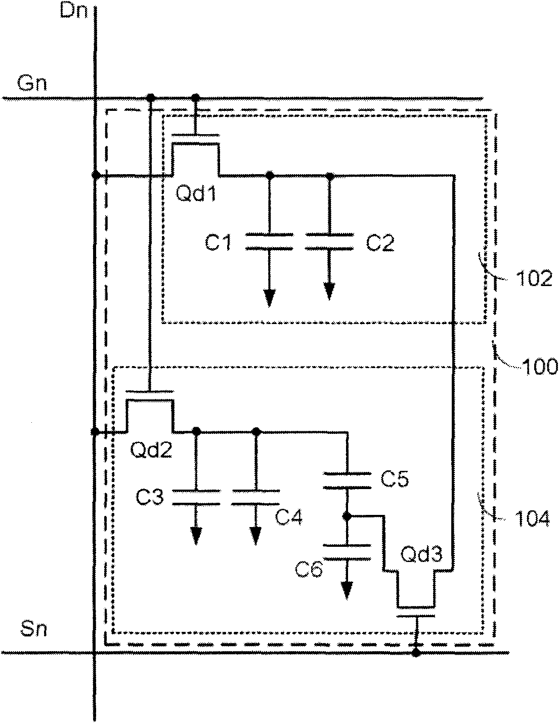
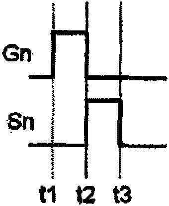
technical field [0001] The present invention relates to a gate driving circuit, in particular to a gate driving circuit on array (GOA for short) applied to a panel with charge sharing pixels. Background technique [0002] Please refer to Figure 1A , which is a schematic diagram of a single charge sharing pixel on a conventional liquid crystal display panel. The charge sharing pixel 100 includes a main area (main area) 104 and a sub area (sub area) 102 . The charge sharing pixel 100 includes three three-switch transistors Qd1 - Qd3 and a plurality of capacitors C1 - C6 . And one charge sharing pixel 100 needs to be connected to two gate lines and one data line, wherein the first gate line can receive the main gate driving signal (main gate driving signal) Gn, and the second gate line can receive the sub-gate driving signal The signal (sub gate driving signal) Sn, the data line can receive the data signal Dn. [0003] Please refer to Figure 1B , which is a schematic diag...

Claims


Application Information

Patent Timeline
Patent Type & Authority Applications(China)
IPC IPC(8): G09G3/36
CPCG09G3/3677G09G2330/023G09G2300/0447G09G3/3659G11C19/28
Inventor 苏国彰陈勇志杨欲忠林致颖
Owner AU OPTRONICS CORP
Learn More