
Phase difference detection method, device and circuit in phase-locked loop circuit

A technology of phase difference detection and phase-locked loop, which is applied in the electronic field, can solve problems such as the influence of measurement accuracy, and achieve the effect of a large signal frequency range

Active Publication Date: 2013-11-06
SHANGHAI HUAWEI TECH CO LTD
View PDF4 Cites 0 Cited by
  • Summary
  • Abstract
  • Description
  • Claims
  • Application Information

AI Technical Summary

Problems solved by technology

[0004] In the above prior art, since the detection clock signal has a multiple relationship with the frequency of the detected clock signal, the frequency of the detection clock signal is represented by F2, the frequency of the detected clock signal is represented by F1, and the measurable phase difference value is represented by n It means that the relationship between the three can be expressed as F2=F1×360 / n, assuming that the frequency of the detected clock signal is 30Mhz, when the frequency of the detected clock signal is 240Mhz, which is 8 times the frequency of the detected clock signal , the 45-degree phase difference can be detected. It can be seen that when the frequency of the detected clock signal increases, the operating frequency of the detected clock signal needs to be multiplied, but the operating frequency range of the detected clock signal is limited by the chip design. In the prior art, the detected clock signal The operating frequency of the signal does not exceed 400 MHz, therefore, the measurement accuracy is affected

Method used


Image

  • Phase difference detection method, device and circuit in phase-locked loop circuit
  • Phase difference detection method, device and circuit in phase-locked loop circuit
  • Phase difference detection method, device and circuit in phase-locked loop circuit

Examples


Embodiment Construction

[0015] Embodiments of the present invention provide a phase difference detection method and device in a phase-locked loop circuit, which are used to improve the precision of phase difference detection, and will be described in detail below.

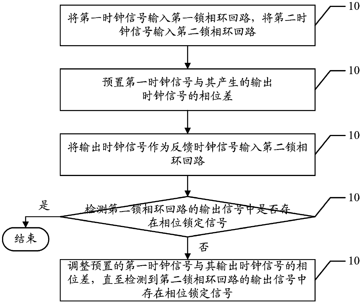
[0016] see figure 1 An embodiment of the phase difference detection method in the phase-locked loop circuit in the embodiment of the present invention can be described as follows.

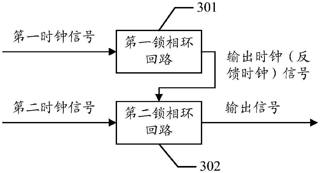
[0017] 101. Input a first clock signal into a first phase-locked loop, and input a second clock signal into a second phase-locked loop.

[0018] For example, the embodiment of the present invention uses the phase locked loop (PLL, Phase Locked Loop) inside the FPGA to detect the phase difference. The phase locked loop is a feedback control circuit that can control the internal oscillation of the loop by using an externally input reference signal. The frequency and phase of the signal, the structural diagram of the phase-locked loop circuit, please refer to ...


PUM


Abstract

The embodiment of the invention discloses a phase difference detection method, device and circuit in a phase-locked loop circuit, and is used for improving the precision of phase difference detection. The method comprises the following steps: setting phase difference of a first clock signal and a clock signal output by the first clock signal in a first phase-locked loop circuit, inputting a second phase-locked loop circuit as a feedback clock signal; detecting whether a phase locking signal in output signals of a second phase-locked loop circuit exists; if the phase locking signal exists, taking the phase difference as the phase difference of the first clock signal and a second clock signal in the second phase-locked loop circuit; and if the phase locking signal does not exist, regulating the set phase difference until a phase locking signal in the output signals is detected.

Description

technical field [0001] The present invention relates to the field of electronic technology, in particular to a phase difference detection method, device and circuit in a phase-locked loop. Background technique [0002] Nowadays, the detection of chip signal phase difference is becoming more and more important, especially in systems that require precise time synchronization, the accuracy of phase difference detection becomes the key to the success of time synchronization. Moreover, with the improvement of system requirements for fault alarm accuracy, phase The application of detection technology in system fault detection is also important. [0003] At present, the method of detecting the phase difference of the internal signal of the element programmable logic gate array (FPGA, Field Programmable Gate Array) usually uses a detection clock signal with a high operating frequency to detect two low-frequency detected clock signals that need to compare phases. The clock signal is...

Claims


Application Information

Patent Timeline
Patent Type & Authority Patents(China)
IPC IPC(8): H03L7/08G01R25/00
Inventor 陈栋杨宇
Owner SHANGHAI HUAWEI TECH CO LTD
Learn More