Double clutch

A dual-clutch, clutch technology, applied to clutches, mechanically driven clutches, fluid-driven clutches, etc., can solve the problem of high manufacturing cost of the clutch cover and achieve the effect of preventing dragging torque

Inactive Publication Date: 2014-03-05
SCHAEFFLER TECH AG & CO KG +1
View PDF4 Cites 0 Cited by
  • Summary
  • Abstract
  • Description
  • Claims
  • Application Information

AI Technical Summary

Problems solved by technology

This clutch cover is expensive to manufacture
In addition, the clutch cover requires axial installation space

Method used


Image

  • Double clutch
  • Double clutch
  • Double clutch

Examples


Embodiment Construction

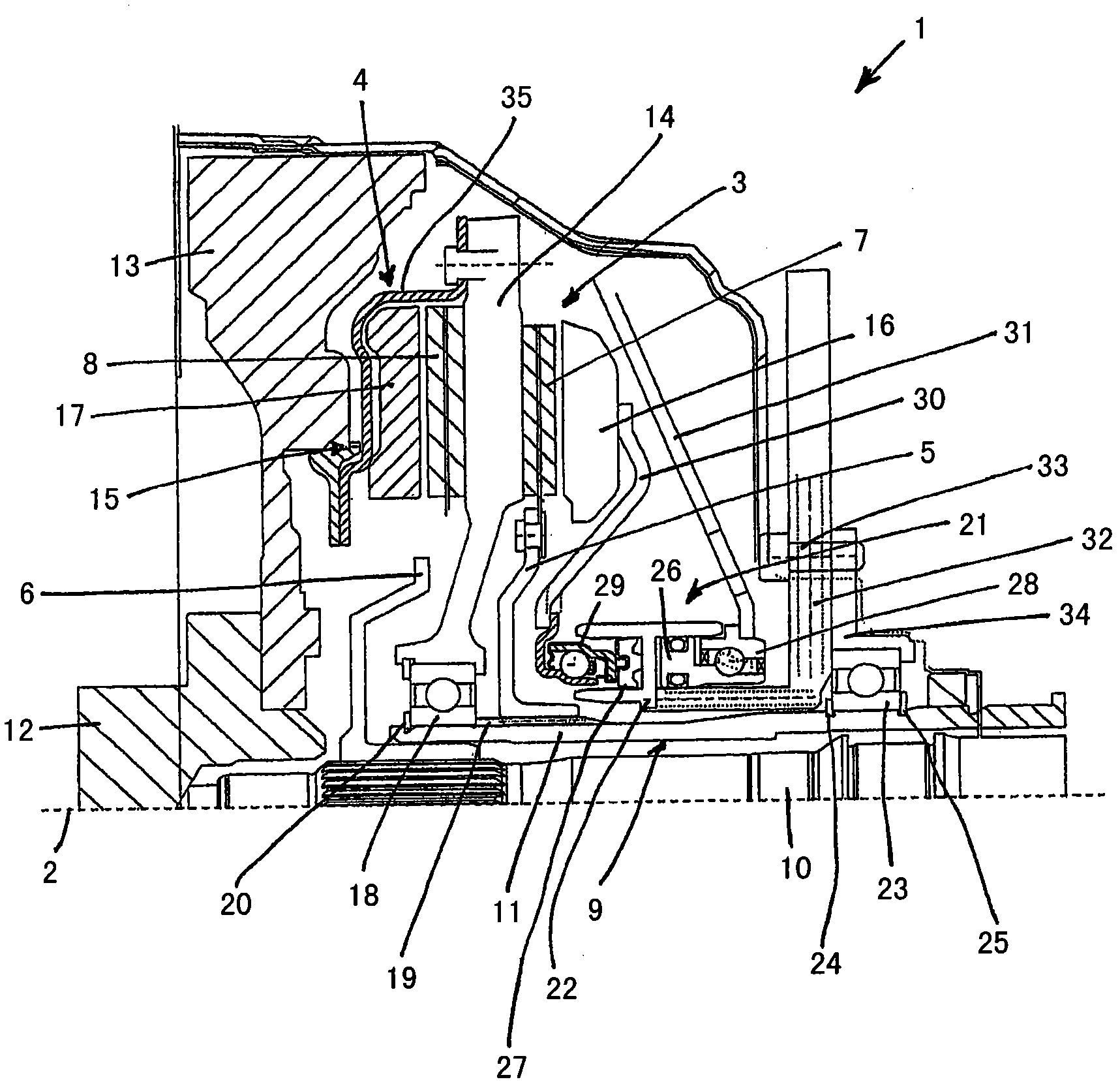
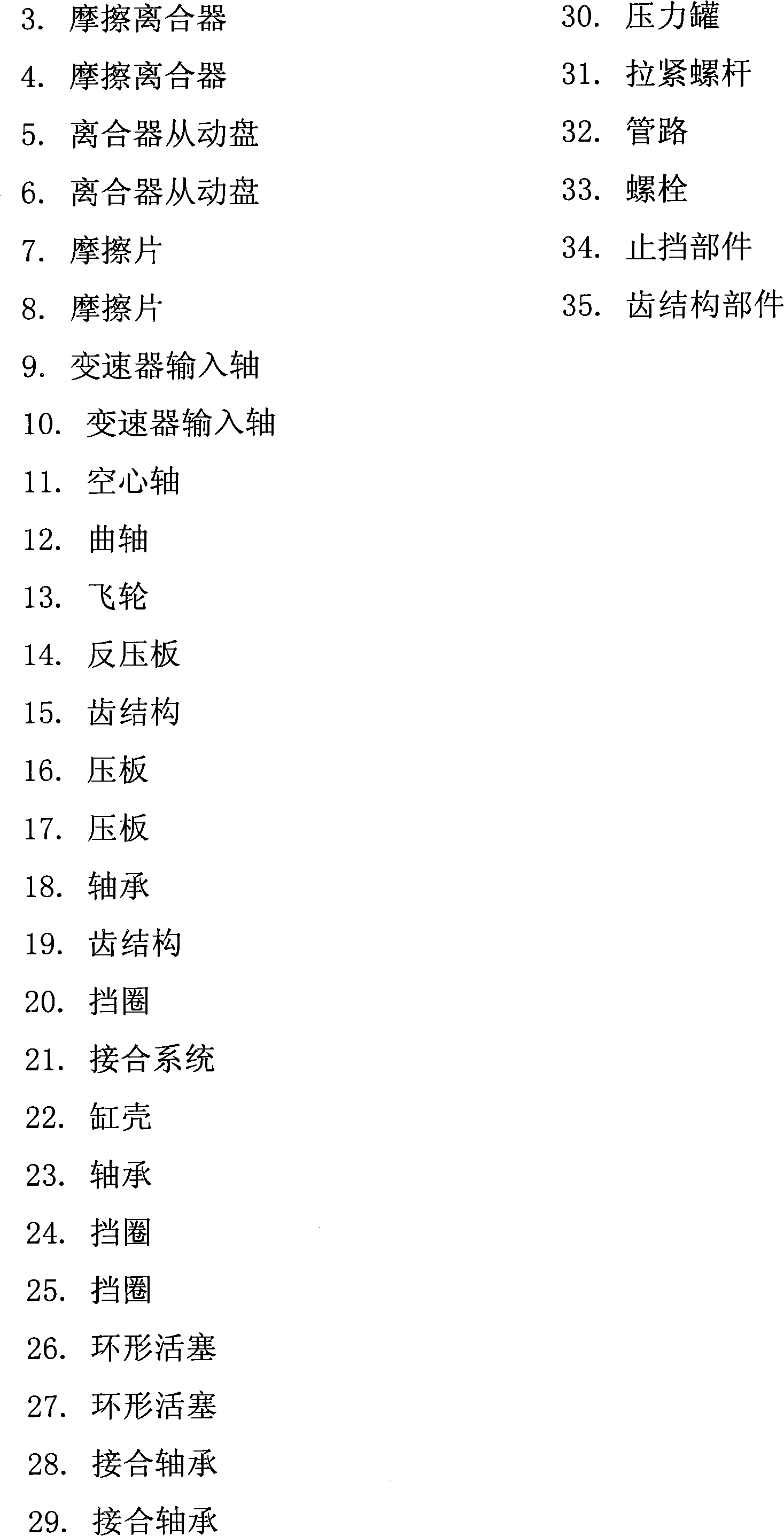
[0010] The invention is described in detail with reference to a single drawing. The figure shows a partial view of a double clutch 1 with two friction clutches 3, 4 above the axis of rotation 2. These friction clutches form a frictional engagement with the friction plates 7, 8 of the clutch disks 5, 6 according to their operation, wherein according to This friction fit transmits a torque introduced into the friction clutches 3 , 4 to the transmission input shafts 9 , 10 . The transmission input shaft 9 is formed as a hollow shaft 11 in which the transmission input shaft 10 is received concentrically.

[0011] The torque provided by the crankshaft 12 of the internal combustion engine (not shown) is transmitted to the dual clutch 1 via a flywheel 13 . In this case, in order to compensate the axial play, a tooth structure 15 is provided between the flywheel 13 and the counter pressure plate 14, which tooth structure is formed by the internal teeth of the flywheel 13 and the exte...


PUM


Abstract

The invention relates to a double clutch comprising two friction clutches, a central back pressure plate and a pressure plate pressurized by a hydrostatic engagement system. In order to be able to propose a cost-effective design having no clutch cover, two axially fixed shaft bearings are provided on the hollow shaft of the double-clutch transmission, said bearings rotatably receiving the back pressure plate and the engagement system such that the power flow can be closed by way of the hollow shaft when actuating the friction clutches.

Description

technical field [0001] The invention relates to a dual clutch having two friction clutches and an engagement system to operate them. Background technique [0002] Such a dual clutch is known from the motor vehicle drive path of a dual clutch transmission comprising two partial drive branches each having a transmission input shaft, wherein one transmission input shaft is formed as a hollow shaft and the other transmission input shaft is introduced concentrically in the The first transmission input shaft. The two transmission input shafts each have an external toothing at their ends, on which a clutch disc and the clutch slaves of the two friction clutches contained in the dual clutch set are received in a non-rotatable manner according to the operation of the engagement system. The disc will be connected to the drive unit. [0003] A double clutch, typically embodied as two friction clutches, comprises a single central counterplate, rotatably mounted on a hollow shaft, whic...

Claims


Application Information

Patent Timeline
Patent Type & Authority Patents(China)
IPC IPC(8): F16D25/10
CPCF16D21/06F16D25/10Y02T10/76F16D2021/0669F16D2021/0615F16C2361/43F16C35/06F16C19/54F16D25/082
Inventor K-L·基米希W·弗格
Owner SCHAEFFLER TECH AG & CO KG
Why Eureka
Try Eureka