Positive-pressure pinch valve

A technology of tube capsule and pressure tube, which is applied in the direction of valves and instruments introduced into the body, can solve the problems of unusable heparin sealing method, cumbersome operation of medical staff, microbial invasion, etc., and achieve simple structure, safety, and freedom from microbial invasion Effect

Active Publication Date: 2011-09-21
张亚根
View PDF11 Cites 8 Cited by
  • Summary
  • Abstract
  • Description
  • Claims
  • Application Information

AI Technical Summary

Problems solved by technology

However, there are certain defects and deficiencies in the above-mentioned technology: before each use, the rubber sealing cap to be punctured on the heparin cap must be partially sterilized, and the rubber plug of the heparin cap must be punctured with an injection needle to be connected with the infusion tube so that the medicinal liquid can pass through The puncture needle tube enters the infusion tube, which is troublesome to operate and has the risk of being stabbed by the needle; in clinical practice, the patient cannot use anticoagulants such as heparin due to certain diseases (such as hemophilia, or blood coagulation disorder). The sealing method of the heparin cap on the infusion tube and the indwelling needle is limited; because there is no anticoagulant such as heparin sodium in the heparin cap, after the infusion of the drug solution, after the treatment is over, the medical staff need to puncture the heparin cap with a syringe and an injection needle. A certain amount of anticoagulant is added to the infusion tube to prevent the infusion tube and indwelling needle plug from being blocked by blood backflow, which makes the operation of medical staff more cumbersome and inconvenient; also because of this operation, the rubber sealing cap is named heparin cap; through The anticoagulant action of injecting heparin sodium with the heparin cap is called tube lock
[0005] The above technical solutions are all based on the positive pressure realization of the needle-free connection, and their common shortcomings are the risk of microbial invasion and the structurally complex factors.

Method used


Image

  • Positive-pressure pinch valve
  • Positive-pressure pinch valve
  • Positive-pressure pinch valve

Examples


Embodiment Construction

[0018] In order to better understand the technical solution of the present invention, the present invention will be described in detail in conjunction with the accompanying drawings.

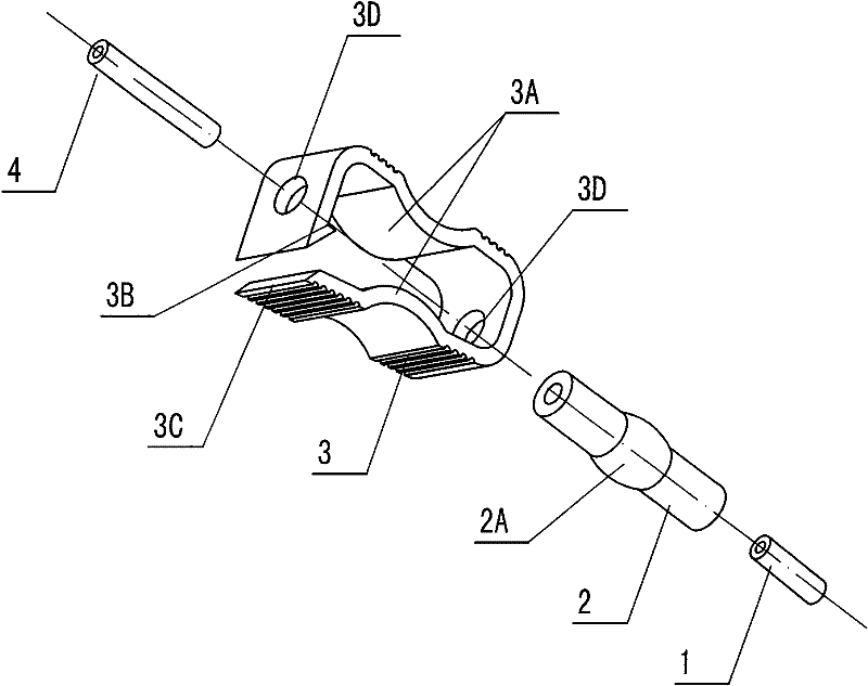
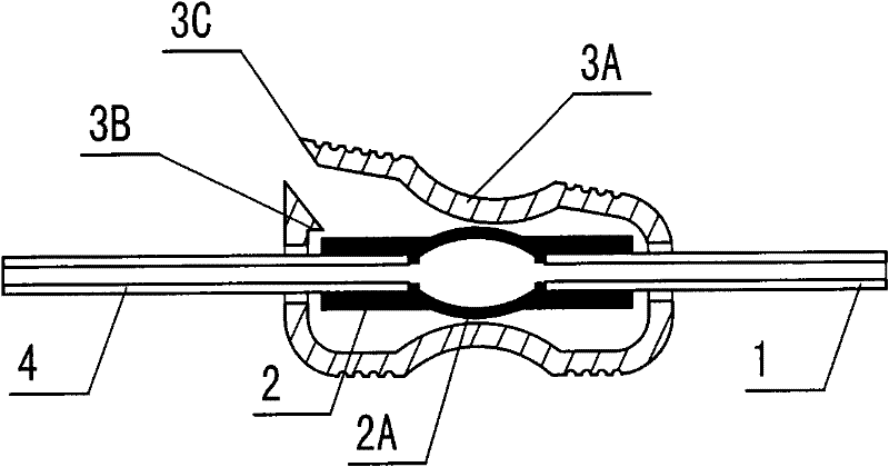
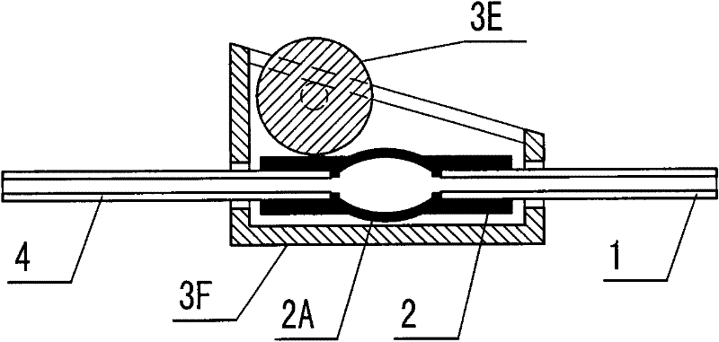
[0019] figure 1 It is a schematic diagram of the assembly structure of the present invention. It can be seen from this figure that a positive pressure capsule valve of the present invention is composed of a front catheter 1, a duct bag 2, a clip 3 and a rear catheter 4, wherein: the front catheter 1 and the rear catheter 4 are bonded On the outlets at both ends of the capsule 2, the capsule 2 is placed in the inner space enclosed by the clip 3; the capsule 2 is a tube section with a balloon 2A protruding outward in the middle, and the inner space of the balloon 2A is larger than the puncture for connection The volume of the needle or plug, the capsule 2 is made of medical elastic material; the clip 3 is a non-closed thin plate that is continuously bent in an approximate "8" shape, and there is a...


PUM


Abstract

The invention relates to a positive-pressure pinch valve which comprises a front guide pipe, a pipe sac, a clip and a back guide pipe. The positive-pressure pinch valve is characterized in that the front guide pipe and the back guide pipe are respectively bonded on outlets at both ends of the pipe sac; and the pipe sac is arranged in an internal space defined by the clip. In the liquid infusion process, the positive-pressure pinch valve is arranged on a retained pipeline; after the infusion process is finished and the connection with the retained part is cancelled, the clip is compressed by hand, so that a protruding tongue on the clip and a fastener are fastened together; meanwhile, two pressure plates on the clip, extending towards the internal space of the clip, forcedly reduce the internal space of a spherical sac on the pipe sac until the internal space is pinched off; and at this moment, liquid in the spherical sac flows in a treatment direction so as to form a positive pressure. When the positive-pressure pinch valve is reused, the spherical sac can automatically recover the smoothness of the infusion pipeline under the action of the own elasticity of the spherical sac by simply unclosing the clip.

Description

technical field [0001] The invention relates to a tube bag valve for liquid infusion, in particular to a positive pressure tube bag valve which can generate positive pressure and prevent venous blood backflow for medical purposes. Background technique [0002] At present, in the process of intravenous infusion treatment, due to the limitations of the disease or the patient's own conditions, long-term repeated infusion treatment is often required, or the drug solution needs to be temporarily injected into the infusion pipeline several times during the infusion process, and enters the blood vessels of the human body to achieve The purpose of treating diseases; in order to reduce the damage to the patient's superficial venous vessels, as well as to alleviate the pain of the patient and the labor intensity of the medical staff, in this case, the structure of the three-way tube and the heparin cap is mostly connected in series in the pipeline of the intravenous infusion set , use...

Claims


Application Information

Patent Timeline
Patent Type & Authority Applications(China)
IPC IPC(8): A61M5/14A61M39/28
Inventor 张亚根王玉峰郭艳
Owner 张亚根
Why Eureka
Try Eureka