

Robot system
A robot system and robot technology, applied in the field of robot systems, can solve problems such as robots exceeding the limit range and increasing equipment costs
- Summary
- Abstract
- Description
- Claims
- Application Information
AI Technical Summary
Problems solved by technology
Method used
Image

Examples
Embodiment 1
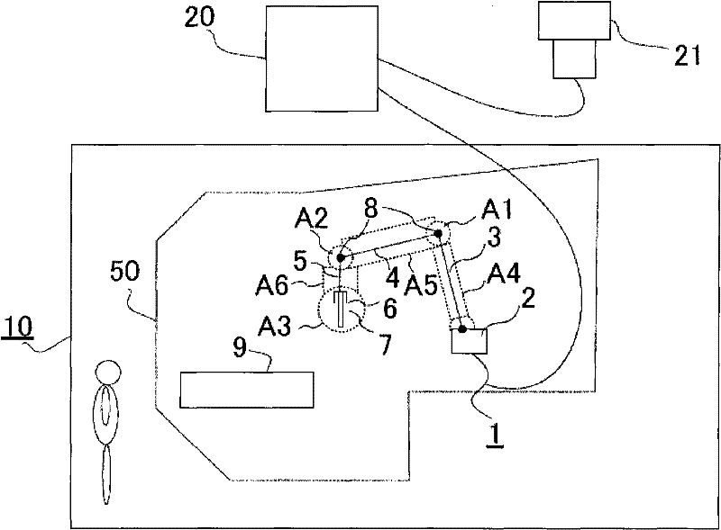
[0068] use figure 1 A robot system including the robot motion limiting method and device of the first embodiment will be described. A physical security fence 10 is provided on the factory floor, and the robot is arranged therein.
[0069] In this example, the robot 1 has a base 2 and three arms 3 , 4 , 5 . A tool 7 is provided on the arm 5 via a gripping device 6 . As the tool 7, a welding torch for arc welding, a torch for spot welding, a hand for carrying, and the like are attached. Joints 8 are used to connect arms 3, 4, and 5, respectively. The workpiece 9 is an object to be welded, a conveyed object, or the like. For example, in the safety fence 10, welding of the workpiece|work 9 and assembly work of a conveyance are performed.
[0070] A necessary signal is sent from the control device 20 to the robot 1, and the arms 3, 4, 5 perform predetermined movements according to a predetermined operation program, and the gripping device 6 or tool 7 moves along a desired traj...
Embodiment 2
[0121] Although the robot motion restriction method in Embodiment 1 is composed of a control program for controlling the robot, in order to further improve safety and reliability, the following device is independently installed to monitor contact with the virtual safety barrier and stop when contact Control of robot motion.
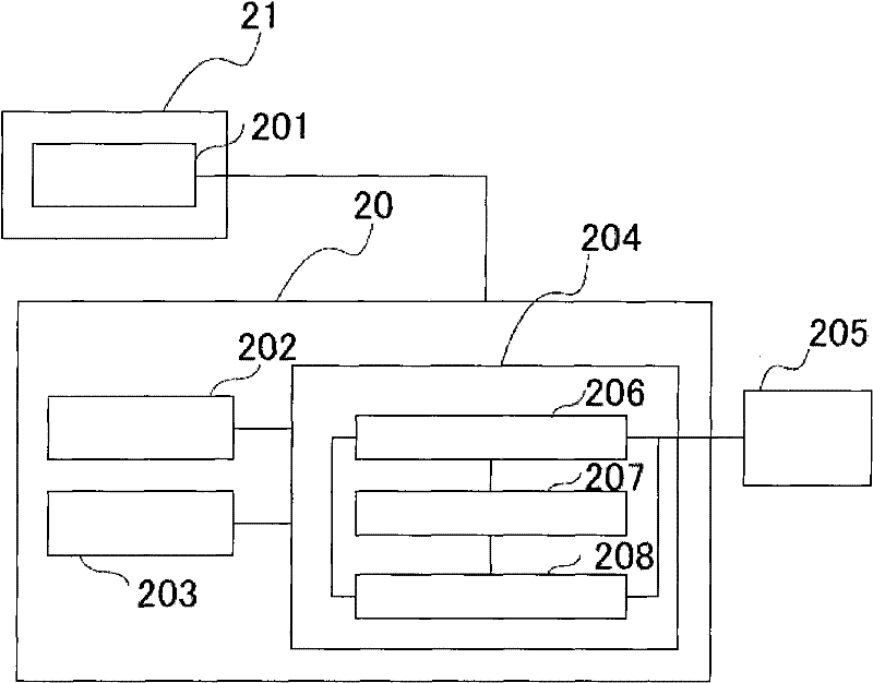
[0122] As the configuration of Example 2, using Image 6 An embodiment in which the aforementioned monitoring and stop control devices are made independent will be described.
[0123] Image 6 is true figure 2 The configuration of the operating region monitoring device 601 is added to the system. The operation area monitoring device 601 obtains the current position of the robot (the position of the workpiece or tool) according to the position of each axis motor 605 through the drive unit 205 in each prescribed monitoring period, and monitors the current position of the robot on the virtual safety barrier. Contact with the virtual safety barrier is ch...
Embodiment 3
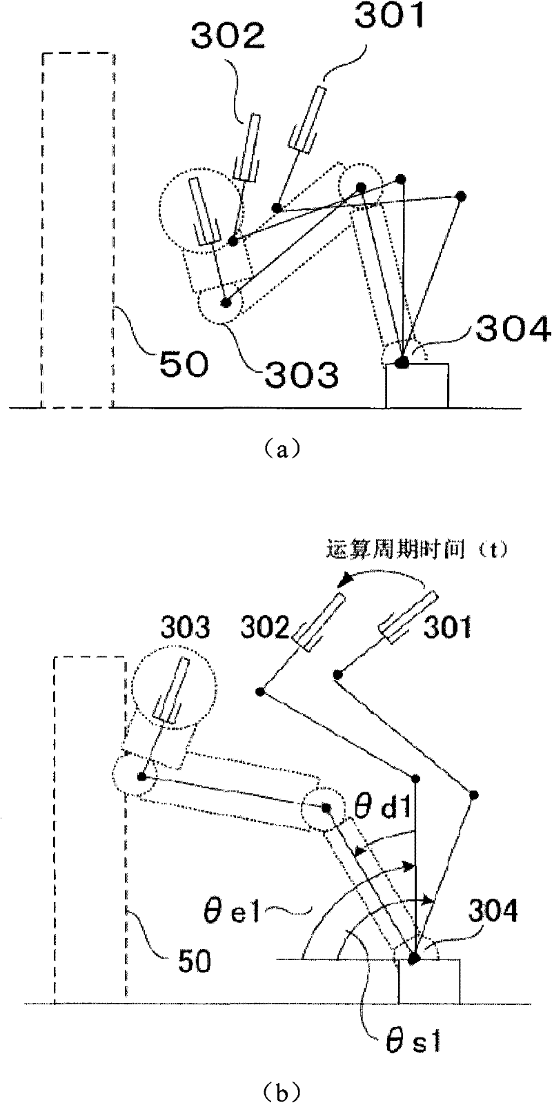
[0143] The robot movement restriction method described in the first and second embodiments is a method of predicting the amount of inertial movement to prevent the robot from contacting the virtual safety fence. This idea can also be applied to the range limit of each axis of the robot.
[0144] use Figure 8 A robot system including the robot motion limiting method and device of the third embodiment will be described. Mechanical safety devices such as mechanical limiters are installed on each axis of a general robot to limit the movement of each axis of the robot. On the other hand, instead of the mechanical limiter, it is possible to reduce the mechanical limiter by defining and monitoring the movable range 60 of each axis.
[0145] Figure 9 It is a figure which shows the other structure of 3rd Embodiment, and demonstrates the embodiment in which the movement restriction of each axis is performed in the apparatus which performs the monitoring and stop control mentioned a...
PUM
 Abstract
Description
Claims
Application Information