Yarn breakage alarm device of yarn pretension regulating mechanism of computer-based flat knitting machine

A technology for adjusting mechanisms and alarm devices, which is applied in knitting, weft knitting, textiles and papermaking, etc. It can solve problems such as relapse and increase labor intensity of workers, and achieve the effect of ensuring reliability and avoiding increased work intensity

Active Publication Date: 2012-11-07
JIANGSU JINLONG TECHNOLOGY CO LTD
View PDF6 Cites 16 Cited by
  • Summary
  • Abstract
  • Description
  • Claims
  • Application Information

AI Technical Summary

Problems solved by technology

[0005] It can be seen that the aforementioned broken yarn alarm signal rod 5 essentially acts as a broken yarn alarm device, but this structure has the disadvantages of easy failure and poor reliability, because Fiber dust is unavoidable at the work site of the computerized flat knitting machine, and the fiber dust often accumulates on the surface of the broken yarn alarm signal rod, causing the electrical conductivity of the yarn broken alarm signal rod with good electrical conductivity to gradually decrease or even disappear. If there is no storage, the signal collector cannot collect the proper signal. That is to say, even if the yarn breaks and the broken yarn alarm signal bar turns over under the action of the yarn guide rod, it cannot give the signal collector the proper signal. Mechanism still works, making fabric flaws
In addition, the surface of the broken yarn alarm signal rod will be oxidized to form an oxide film, which will also lead to the aforementioned disadvantages
[0006]The current disposal method can only be that the on-line staff frequently cleans the surface of the broken yarn alarm signal pole in a regular or irregular manner, but this method increases the It increases the labor intensity of the workers, and once it is neglected to clean it in time, it will relapse

Method used


Image

  • Yarn breakage alarm device of yarn pretension regulating mechanism of computer-based flat knitting machine
  • Yarn breakage alarm device of yarn pretension regulating mechanism of computer-based flat knitting machine
  • Yarn breakage alarm device of yarn pretension regulating mechanism of computer-based flat knitting machine

Examples


Embodiment

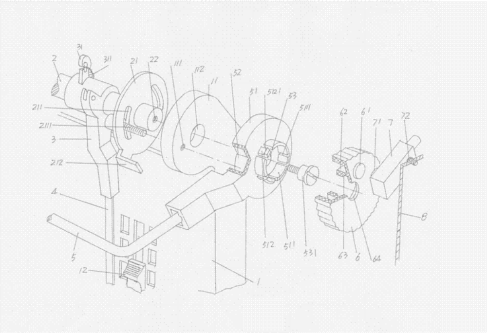
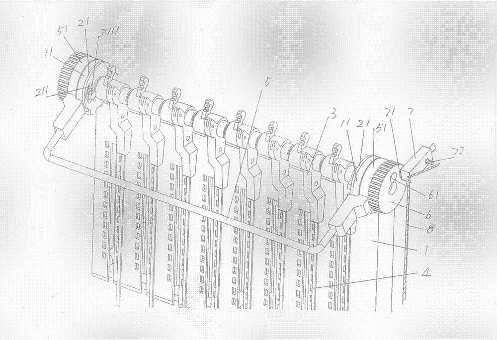
[0022] please see figure 1 , the yarn pretension adjustment mechanism of the computerized flat knitting machine is given. The yarn pretension adjustment mechanism includes a base plate 1, a fixed shaft 2, a set of yarn guide arms 3 and a set of yarn guide arms 3 equal in number to The yarn guide rod 4 and the two ends of the substrate 1 facing the fixed shaft 1 each extend with a fixed ear 11, the fixed ear 11 is fixed to the fixed shaft 2 through the fixed ear hole 112 thereon, and the body of the substrate 1 is movable. There is a group of tension spring tension adjustment sliders 12 (8 in this embodiment), one end of a group of yarn guide arms 3, that is, the base, is rotatably sleeved on the fixed shaft 2, and the ends of each yarn guide arm 3, that is, the base An extension spring hanging foot 31 is extended, one end of an extension spring 311 is fixed on the extension spring hanging foot 31, and the other end of the extension spring 311 corresponds to the bottom of th...


PUM


Abstract

The invention discloses a yarn breakage alarm device of a yarn pretension regulating mechanism of a computer-based flat knitting machine, belonging to the field of computer-based flat knitting machines. The yarn pretension regulating mechanism comprises a substrate provided with a tension-spring tensile force regulating slider, a fixed shaft, yarn guiding arms and yarn guiding rods. The yarn breakage alarm device comprises a yarn breakage alarm signal rod, and the yarn breakage alarm signal rod is arranged on the fixed shaft and corresponds to the upside of the yarn guiding rod. The yarn breakage alarm device is characterized by further comprising a regulating knob and a signal collector, wherein one side of the regulating knob towards a turntable is matched with the turntable, one side of the regulating knob towards the signal collector is fixedly provided with a magnet, the signal collector is fixed on a box base and corresponds to the magnet, and the signal collector is electrically connected with a controller of the computer-based flat knitting machine through a circuit. The yarn breakage alarm device has the advantages of being capable of playing the role in timely alarming and shutting down, guaranteeing the reliability and non-malfunction of yarn breakage alarm, and favorably preventing increased work load to operators due to artificial cleaning.

Description

technical field [0001] The invention belongs to the technical field of computerized flat knitting machines, and in particular relates to a yarn breakage alarm device for a yarn pretension adjustment mechanism of a computerized flat knitting machine. Background technique [0002] Since the yarn pretension adjustment mechanism is usually installed on the upper side of one end of the computerized flat knitting machine, it is customary in the industry to call it a side antenna pretension adjustment mechanism. The yarn fed by the yarn feeder passes through the pretension adjustment mechanism. The head of the knitting mechanism of the computerized flat knitting machine is introduced. The self-evident function of the yarn pretension adjustment mechanism is to adjust the tension of the yarn to ensure the effect of yarn feeding, because the tension of the yarn is not constant, it is affected by its own material (the fiber material that constitutes the yarn) It is changed by the infl...

Claims


Application Information

Patent Timeline
Patent Type & Authority Patents(China)
IPC IPC(8): D04B35/14D04B15/56
Inventor 金永良兰先川孙健
Owner JIANGSU JINLONG TECHNOLOGY CO LTD
Why Eureka
Try Eureka