
Patsnap Eureka
For R&D, Patsnap Eureka makes reading and utilizing patents & technical documents easy.
Patsnap Eureka AIR
Designed for self-driven R&D workflows. Generate viable solutions, solve complex R&D challenges, empower your innovation with AI.

Patsnap Eureka Materials
Designed for material experts only. Revolutionize your material R&D, from search, analyze, to developing new materials.

TechResearch
Generate reliable direction feasibility study reports for your R&D in just a few steps.

TechSeek
Discover and master advanced knowledge NOW. Basics, ideas, possibilities, all at once.

TechMind
As an expert in R&D Theories, TechMind can generates customized viable solutions instantly.

TechRisk
Analyze your overall solution with one click, know your potential R&D risks in advance.

TechMonitor
Get weekly tech updates, stay abreast of the latest tech innovations and key insights.
Redundant pitch system
A technology of pitch system and pitch drive, which is applied in the control of wind turbines, engine functions, engines, etc., which can solve the problems of insufficient redundancy and achieve reliable transmission
- Summary
- Abstract
- Description
- Claims
- Application Information
AI Technical Summary
Problems solved by technology
Method used
Image

Examples
Embodiment Construction
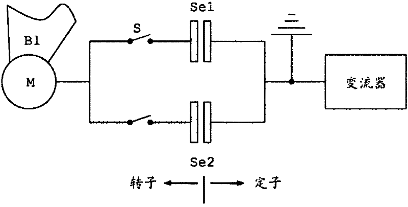
[0041] Depend on Figure 1a It can be seen that the pitch drive of the pitch system according to the first embodiment of the present invention, wherein the motor M mechanically coupled with the rotor blade B1 can pass through a first series circuit composed of a switch S and a first conductive slip ring Se1 Electrically connected to a converter. The motor M can also be electrically connected to the converter through a second series circuit composed of a switch and a second conductive slip ring Se2, wherein the second series circuit is connected in parallel with the first series circuit. Therefore, the motor M can be electrically connected to the converter through the first conductive slip ring Se1 or through the second conductive slip ring Se2 by means of the switch. The conductive slip rings Se1 and Se2 are preferably each designed as a slip ring unit. The electrically conductive slip ring forms in particular a slip ring arrangement.
[0042] If one conductive slip ring is...
PUM
 Abstract
Description
Claims
Application Information
 - R&D Engineer
- R&D Manager
- IP Professional
- Industry Leading Data Capabilities
- Powerful AI technology
- Patent DNA Extraction
Browse by: Latest US Patents, China's latest patents, Technical Efficacy Thesaurus, Application Domain, Technology Topic, Popular Technical Reports.
© 2024 PatSnap. All rights reserved.Legal|Privacy policy|Modern Slavery Act Transparency Statement|Sitemap|About US| Contact US: help@patsnap.com