Multi-core optical fiber
A multi-core fiber, fiber core technology, applied in multi-core fiber, cladding fiber, optics, etc., to reduce transmission loss, reduce nonlinearity, and reduce crosstalk.
- Summary
- Abstract
- Description
- Claims
- Application Information
AI Technical Summary
Problems solved by technology
Method used
Image

Examples
no. 1 Embodiment approach
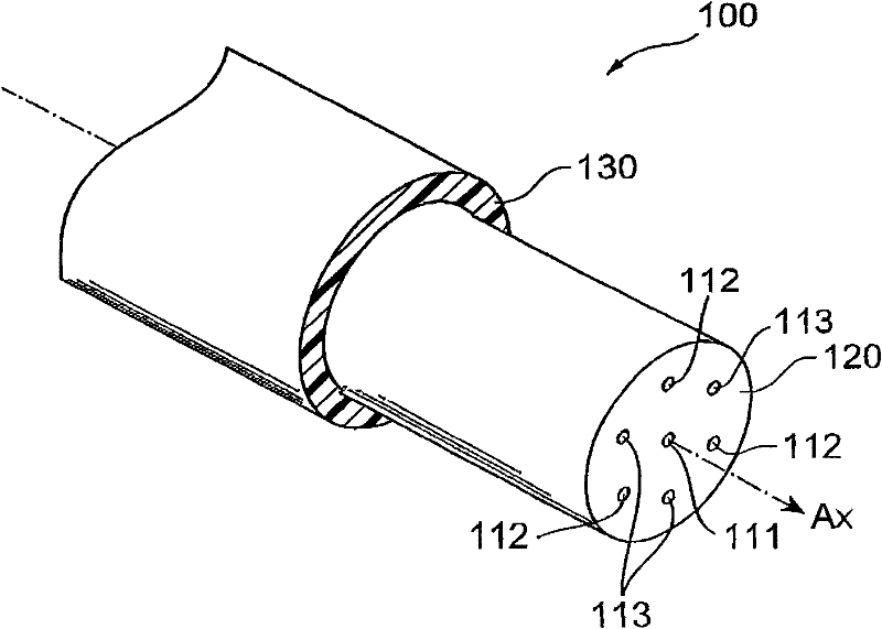
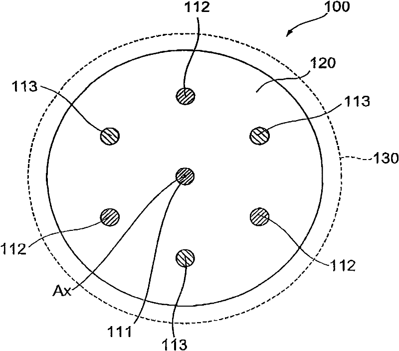
[0032] figure 1 It is a diagram showing a schematic configuration of the first embodiment of the multi-core optical fiber according to the present invention. in addition, figure 2 It is a diagram showing the cross-sectional structure of the multi-core optical fiber according to the first embodiment. figure 1 The multicore fiber 100 is along the central axis A x The optical fiber extending (a predetermined axis coincident with the longitudinal direction of the multi-core optical fiber 100) has: a plurality of cores 111-113; x The orthogonal plane has a circular cross section; and the cladding part 130 is provided on the outer periphery of the cladding. Disposed within the cladding 120 is a central core 111 disposed at the center of the cladding and extending along the central axis A x extension; and 2 kinds of peripheral cores 112, 113, which are arranged at different positions from the central core 111, and along the central axis A x extend. In addition, the periphera...
no. 2 Embodiment approach
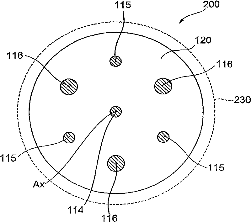
[0039] image 3 It is a diagram showing the cross-sectional structure of the second embodiment of the multi-core optical fiber according to the present invention. The multi-core optical fiber 200 according to the second embodiment is different from the multi-core optical fiber 100 according to the first embodiment ( figure 2 ) are different in the following respects. That is, the relative refractive index differences between the central core and the peripheral cores are equal to each other, and the diameters of adjacent peripheral cores are different from each other. In addition, in image 3 in, with figure 2 Similarly, the central axis A of the multi-core fiber 200 is shown x Orthogonal plane consistent sections.
[0040] Specifically, the multi-core optical fiber 200 according to the second embodiment includes: a plurality of cores 114 to 116; a cladding 120 covering the plurality of cores 114 to 116; and a cladding 230 provided on the outer periphery of the cladding...
PUM
| Property | Measurement | Unit |
|---|---|---|
| diameter | aaaaa | aaaaa |
Abstract
Description
Claims
Application Information
 - R&D
- Intellectual Property
- Life Sciences
- Materials
- Tech Scout
- Unparalleled Data Quality
- Higher Quality Content
- 60% Fewer Hallucinations
Browse by: Latest US Patents, China's latest patents, Technical Efficacy Thesaurus, Application Domain, Technology Topic, Popular Technical Reports.
© 2025 PatSnap. All rights reserved.Legal|Privacy policy|Modern Slavery Act Transparency Statement|Sitemap|About US| Contact US: help@patsnap.com