
A tunnel leaky cable communication system

A communication system and leaky cable technology, which is applied in the field of tunnel leaky cable communication systems, can solve the problems of reducing construction costs and difficulties, and achieve the effect of reducing deployment costs

Active Publication Date: 2021-09-28
北京凯博无线科技有限公司
View PDF6 Cites 0 Cited by
  • Summary
  • Abstract
  • Description
  • Claims
  • Application Information

AI Technical Summary

Problems solved by technology

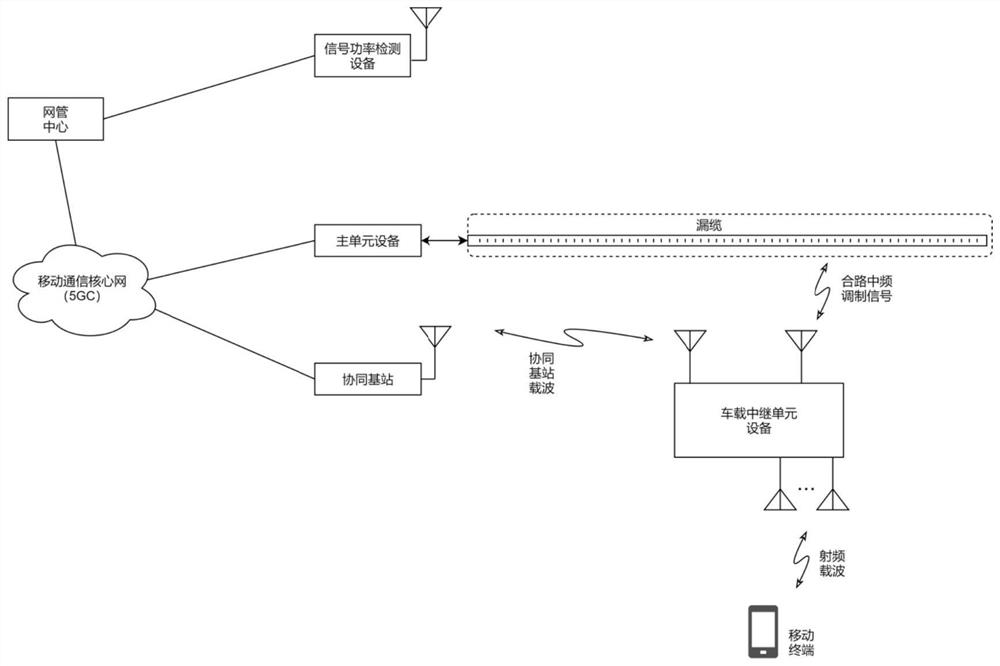
[0004] In order to solve the problem that the existing leaky cable solution cannot continue to be applicable to the tunnel in-vehicle coverage application for mobile communication signals with higher carrier frequencies (such as 5G signals), the purpose of the present invention is to provide a new type of tunnel leaky cable communication system, that is, in the leaky cable The signal source part of the cable adopts the main unit equipment that outputs the multi-channel intermediate frequency modulation signal, and then uses the leaky cable to transmit the intermediate frequency modulation signal and radiates it to the space in the tunnel, and then uses the vehicle mounted on the car body of the train running in the tunnel The relay unit equipment converts the intermediate frequency modulation signal into a multi-channel radio frequency carrier signal at a target operating frequency higher than the cut-off frequency of the leaky cable, covering the inside of the car, not only does not need to redeploy a new type of leaky cable that supports a higher cut-off frequency, It greatly reduces the deployment cost, construction cost and difficulty of the leaky cable coverage scheme for mobile communication signals with high carrier frequency (especially 5G signals), and supports multi-channel communication; System synchronization and equipment management ensure the robustness of the on-board relay unit equipment

Method used


Image

  • A tunnel leaky cable communication system
  • A tunnel leaky cable communication system
  • A tunnel leaky cable communication system

Examples


Embodiment 1

[0080] Such as Figure 1~5 As shown, the tunnel leaky cable communication system provided in this embodiment includes a main unit device, a leaky cable, a vehicle-mounted relay unit device, a coordinated base station, a mobile communication core network, and a network management center, wherein the main unit device is A multi-channel signal processing device; the main unit device is used to perform baseband processing on the control plane and user plane data streams from the mobile communication core network, generate multi-channel downlink I / Q data, and then modulate to obtain Based on the multi-channel intermediate frequency downlink modulation signals of different intermediate frequency carriers, then the multi-channel intermediate frequency downlink modulation signals are combined and processed to obtain the combined intermediate frequency downlink modulated signal, and finally the combined intermediate frequency downlink modulated signal is transmitted to the drain cable,...

Embodiment 2

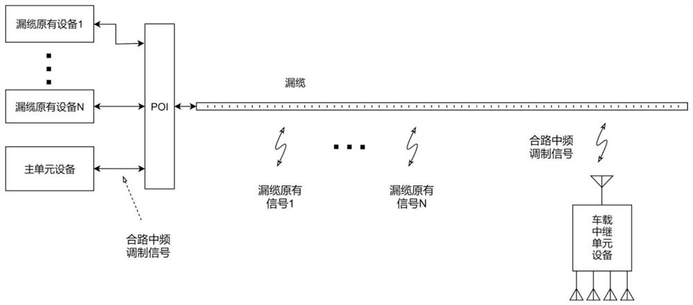
[0100] Such as Figure 6 As shown, on the basis of the mobile communication signal coverage scheme in the tunnel in the foregoing embodiment 1, this embodiment also discloses another technical solution for specifically transmitting coordinated base station signals, that is, the difference from the foregoing embodiment 1 is: A platform-in (POI) connects the signal of the coordinated base station into the leaky cable. The carrier signal of the coordinated base station is indirectly wirelessly transmitted to the vehicle-mounted relay unit device through the leaky cable, so that the vehicle-mounted relay unit device is registered on the carrier of the coordinated base station, and the entire tunnel is obtained from the carrier of the coordinated base station The synchronization signal of the leaky cable communication system establishes a data connection with the network management center, and then executes corresponding coordinated actions to complete configuration and maintain wo...

Embodiment 3

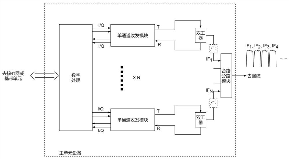
[0103] Such as Figure 7 As shown, this embodiment also discloses a technical solution for solving the problem of excessive signal loss in the transmission process on the basis of the mobile communication signal coverage scheme in the tunnel of the foregoing embodiment 1 or 2, which is the same as the foregoing embodiment 1 or 2. The difference between the two is that a power amplifier (PA, Power Amplifier) ​​is connected in series in the downlink communication link between the downlink sending port of the single-channel transceiver module and the duplexer, and between the duplexer and the duplexer A low noise amplifier (LNA, Low Noise Amplifier) ​​is connected in series in the uplink communication link between the uplink receiving ports of the single-channel transceiver module.

[0104] To sum up, on the basis of the technical effects of Embodiment 1 or 2, this embodiment also has the following technical effects: (1) The gain of the intermediate frequency downlink modulation ...


PUM


Abstract

The invention relates to the technical field of mobile communication, and discloses a tunnel leaky cable communication system, that is, a main unit device that outputs a multi-channel intermediate frequency modulation signal in the source part, and then uses the leaky cable to transmit the intermediate frequency modulation signal and radiates to Space in the tunnel, and then use the vehicle-mounted relay unit equipment placed on the car body of the train running in the tunnel to convert the intermediate frequency modulation signal into a multi-channel radio frequency carrier signal at a target operating frequency higher than the cut-off frequency of the leaky cable, covering To the interior of the carriage, not only does it not need to redeploy new leaky cables that support higher cut-off frequencies, it greatly reduces the deployment cost, construction cost and difficulty of leaky cable coverage solutions for mobile communication signals with higher carrier frequencies (especially 5G signals), and supports Multi-channel communication; on the other hand, the system synchronization and equipment management of the on-board relay unit equipment are carried out by using cooperative base stations, which ensures the robustness of the on-board relay unit equipment.

Description

technical field [0001] The invention belongs to the technical field of mobile communication, and relates to a transmission and coverage scheme of mobile communication signals in underground space, which can be applied to the mobile communication signal coverage of the compartment space in a tunnel, and in particular relates to a tunnel leaky cable communication system. Background technique [0002] The subway tunnel scenario is one of the important scenarios in the deployment of mobile communication networks. Due to its complex and multi-block terrain and vehicle body penetration loss, it is more difficult to cover mobile communication networks in this scenario. Currently, coverage schemes based on leaky coaxial cables (referred to as leaky cables) are commonly used in subway tunnel scenarios to solve this difficulty. The leaky cable is a special coaxial cable. The difference from the ordinary coaxial cable is that there are equally spaced slots for radiation on the outer co...

Claims


Application Information

Patent Timeline
Patent Type & Authority Patents(China)
IPC IPC(8): H04B7/0413H04L5/14H04L27/26H04W4/42
CPCH04B7/0413H04L5/14H04L27/2627H04W4/42
Inventor 周强徐元达杨宝义刘光华
Owner 北京凯博无线科技有限公司
Learn More