Fixing device and image forming apparatus
A technology for fixing parts and means, applied in the fields of electric recording process using charge pattern, equipment for electric recording process using charge pattern, and electrography, etc., which can solve problems such as clogging, inability to carry out smooth transportation, and reduced quality of printed matter
- Summary
- Abstract
- Description
- Claims
- Application Information
AI Technical Summary
Problems solved by technology
Method used
Image

Examples
Embodiment approach 1
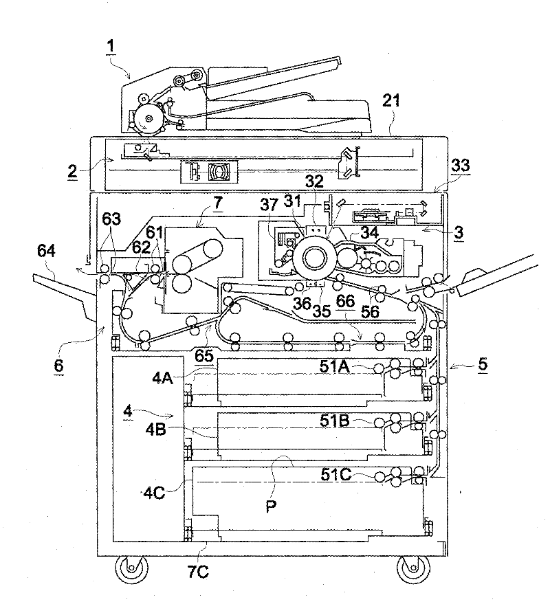
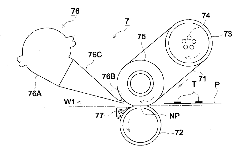
[0046] like image 3 As shown, the fixing device 7 according to Embodiment 1 of the present invention includes: a fixing belt 71 as a fixing member; a lower pressure roller 72 as a pressure member; a heating roller 73 ; a heater 74 ; and an upper pressure roller 75 .
[0047]The fixing belt 71 is composed of an endless transmission belt in which an elastic layer such as silica gel is formed on a heat-resistant film substrate such as PI (polyimide), and a PFA (polytetrafluoroethylene-perfluoroalkyl vinyl ether) layer is further formed thereon. ), PTFE (polytetrafluoroethylene) and other fluororesin release surface layers. The lower pressure roller 72 and the upper pressure roller 75 are composed of rollers. These rollers form a silicone elastic layer on the metal tube base, and form a fluororesin release surface layer such as PFA or PTFE on the elastic layer. The lower pressure roller 72 forms a fixing nip NP that brings the recording material into contact with the fixing belt...
Embodiment 1
[0093] Device structure: image 3 The shown fixing device specifically has the following structure.
[0094] Heating roller 73: Outer diameter 90mm, PTFE coating (built-in heater: 1200W×2,750W×2,500W)
[0095] Upper pressure roller 75: outer diameter 90mm, 17mm thick silicone (10°JISA), surface layer PTFE coating
[0096] Lower pressure roller 72: outer diameter 90mm, 2mm thick silicone (10°JISA), surface layer 30μm thick PFA sleeve (built-in heater: 700W)
[0097] Fixing belt 71: outer diameter 168mm, 70μm thick polyimide base, 200μm thick silicone (15°JISA), 30μm thick PFA sleeve
[0098] Fixing load: 2000N Belt tension: 250N
[0099] Fixing belt control temperature: 160~200℃
[0100] Lower pressure roller control temperature: 80~120℃
[0101] Speed: 500mm / s
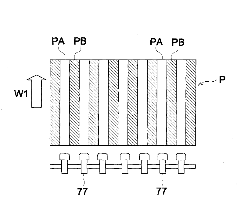
[0102] Separation claw 77: base material PI, surface layer PFA coating.
[0103] Tip shape: R 0.05 or less, tip width WD 12mm
[0104] Number: 7
[0105] Claw tip position: Set the claw tip at 12mm fro...
Embodiment 2
[0117] Adopted Figure 7 The shown fixing unit, that is, the fixing unit 7 is equipped with an air separation device 76 and an air separation device 78 .
[0118] The nozzles of the air separation unit 78: 1mm×65(5mm pitch)
[0119] Compressor: 0.75kW 0.8MPa 0.00125m 3 / s
[0120] (reciprocating / no oil supply type) accumulator tank capacity 0.05m 3
[0121] Direct acting solenoid valve: capacity 0.001m 3 / s(100kPa)×2
[0122] Response speed: ~20ms
[0123] Air spitting time: about 50ms (A4 horizontal 100ppm each passing time: 600ms)
[0124] Others Image formation and fixing were carried out under the same conditions as in Example 1.
[0125] As a result, the fixing progressed well, and the recording material after the fixing treatment had no streak-like unevenness.
PUM
 Abstract
Description
Claims
Application Information
 - R&D
- Intellectual Property
- Life Sciences
- Materials
- Tech Scout
- Unparalleled Data Quality
- Higher Quality Content
- 60% Fewer Hallucinations
Browse by: Latest US Patents, China's latest patents, Technical Efficacy Thesaurus, Application Domain, Technology Topic, Popular Technical Reports.
© 2025 PatSnap. All rights reserved.Legal|Privacy policy|Modern Slavery Act Transparency Statement|Sitemap|About US| Contact US: help@patsnap.com