Interface for liquid metal bearing and manufacture method thereof

A liquid metal and alloy technology, applied in the field of x-ray tubes, can solve problems such as high cost

Inactive Publication Date: 2011-09-21
GENERAL ELECTRIC CO
View PDF4 Cites 6 Cited by
  • Summary
  • Abstract
  • Description
  • Claims
  • Application Information

AI Technical Summary

Problems solved by technology

However, the molybdenum base metal tends to be costly, and alternative SGBs with molybdenum coatings only in the areas in contact with the gallium often include costly brazing steps
Processing of molybde

Method used


Image

  • Interface for liquid metal bearing and manufacture method thereof
  • Interface for liquid metal bearing and manufacture method thereof
  • Interface for liquid metal bearing and manufacture method thereof

Examples


Embodiment Construction

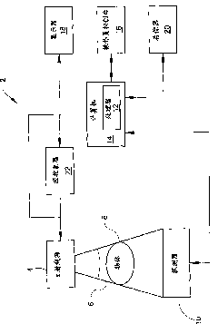
[0096] figure 1 is a block diagram of one embodiment of an x-ray imaging system 2 designed to both acquire raw image data and process the image data for display and / or analysis in accordance with the present invention. Those skilled in the art will appreciate that the present invention is applicable to numerous medical imaging systems using x-ray tubes, such as x-ray or mammography systems. Other imaging systems, such as computed tomography (CT) systems and digital radiography (RAD) systems that acquire a certain amount of image three-dimensional data, also benefit from the invention. The following discussion of imaging system 2 is only an example of such an embodiment and is not intended to be limiting in form.

[0097] like figure 1 As shown in , imaging system 2 includes an x-ray tube or source 4 configured to project an x-ray beam 6 through an object 8 . Object 8 may include a human body, piece of luggage, or other object that is desired to be scanned. The x-ray source...


PUM


Abstract

The invention relates to an interface for a liquid metal bearing and a manufacture method thereof. Specifically, an x-ray tube (4) comprises a cathode (36) and a target assembly located to receive electron emitted by the cathode. The target assembly comprises a target (32) and a spiral groove bearing (SGB) (34) configured to support the target (32). The SBG (34) comprises a fixed component (41) having a first surface and attached on first materials (72, 74, 76) on the first surface and having a second surface and attached on second materials (70, 78, 80) on the second surface, wherein the fixed component (41) is located to form clearances between the first materials (72, 74, 76) and the second materials (70, 78, 80); and liquid metals (50) located in the clearances, wherein at least one of the first and second materials (70, 72, 74, 76, 78, 80) contains tantalum.

Description

[0001] Cross References to Related Applications [0002] This application is a continuation-in-part of US Patent Application Serial No. 12 / 410,518 filed March 25, 2009 and claims priority therefrom. technical field [0003] Embodiments of the invention relate generally to x-ray tubes, and more particularly to x-ray tubes incorporating spiral groove bearings (SGB) therein. Background technique [0004] An x-ray system typically includes an x-ray tube, a detector, and a support structure for the x-ray tube and detector. In operation, an imaging table on which an object is positioned is located between the x-ray tube and the detector. An x-ray tube typically emits radiation, such as x-rays, towards an object. This radiation typically passes through the object on the imaging table and impinges on the detector. As the radiation passes through the object, the internal structure of the object causes spatial variations in the radiation received at the detector. The detectors the...

Claims


Application Information

Patent Timeline
IPC IPC(8): H01J35/24H01J35/08H01J35/02
Inventor M·A·拉思罗普
Owner GENERAL ELECTRIC CO
Why Eureka
Try Eureka