Spiral Groove Bearing Assembly With Minimized Deflection

Active Publication Date: 2020-01-09
GENERAL ELECTRIC CO
View PDF4 Cites 0 Cited by
  • Summary
  • Abstract
  • Description
  • Claims
  • Application Information

AI Technical Summary

Benefits of technology

[0013]In one exemplary embodiment of the present disclosure, a liquid metal or spiral groove bearing structure for an x-ray tube and associated process for manufacturing the bearing structure is provided in which journal bearing sleeve is formed with a number of structures thereon that function to dissipate heat transmitted to the sleeve during operation of the bearing a

Problems solved by technology

This places stringent demands on the bearings and the material forming the anode structure, i.e., the anode target and the shaft supporting the target.
However, liquid metals tend to be highly reactive and corrosive.
However, these materials have a low weldability and are difficult to machine, such that bearing components of these materials are hard to manufacture without surface imperfections that enable leaks to occur in the seals.
Also, due to the low galling/wear properties of the refractory materials, these surface imperfections, even if not present after machining, can occur during normal use of the tube resulting in the formation of fluid leaks, thereby shortening the useful life of the tube.
However, one si

Method used


Image

  • Spiral Groove Bearing Assembly With Minimized Deflection
  • Spiral Groove Bearing Assembly With Minimized Deflection
  • Spiral Groove Bearing Assembly With Minimized Deflection

Examples


Embodiment Construction

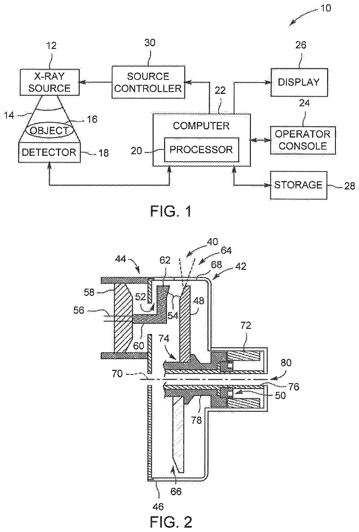
[0029]FIG. 1 is a block diagram of an embodiment of an imaging system 10 designed both to acquire original image data and to process the image data for display and / or analysis in accordance with embodiments of the invention. It will be appreciated by those skilled in the art that various embodiments of the invention are applicable to numerous medical imaging systems implementing an x-ray tube, such as x-ray or mammography systems. Other imaging systems such as computed tomography (CT) systems and digital radiography (RAD) systems, which acquire image three dimensional data for a volume, also benefit from the invention. The following discussion of x-ray system 10 is merely an example of one such implementation and is not intended to be limiting in terms of modality.

[0030]As shown in FIG. 1, imaging system 10 includes an x-ray tube or source 12 configured to project a beam of x-rays 14 through an object 16. Object 16 may include a human subject, pieces of baggage, or other objects des...


PUM

PropertyMeasurementUnit
Frequencyaaaaaaaaaa
Frequencyaaaaaaaaaa
Frequencyaaaaaaaaaa

Abstract

A liquid metal or spiral groove bearing structure for an x-ray tube and associated process for manufacturing the bearing structure is provided in which journal bearing sleeve is formed with a number of structures thereon that function to dissipate heat transmitted to the sleeve during operation of the bearing assembly within the x-ray tube to minimize thermal deformation of the sleeve, thereby minimizing gap size alteration within the bearing assembly. The structures formed within the sleeve are slots disposed within the section of the sleeve in which the highest temperature gradients develop. The slots enable an increase in thermal conductance away from the sleeve while minimizing the stresses created from the deformation of the portion(s) of the sleeve between the slots.

Description

BACKGROUND OF THE INVENTION[0001]The invention relates generally to x-ray tubes, and more particularly to structures and methods of assembly for the spiral groove bearing (SGB) utilized in an x-ray tube.[0002]X-ray systems may include an x-ray tube, a detector, and a support structure for the x-ray tube and the detector. In operation, an imaging table, on which an object is positioned, may be located between the x-ray tube and the detector. The x-ray tube typically emits radiation, such as x-rays, toward the object. The radiation passes through the object on the imaging table and impinges on the detector. As radiation passes through the object, internal structures of the object cause spatial variances in the radiation received at the detector. The detector then emits data received, and the system translates the radiation variances into an image, which may be used to evaluate the internal structure of the object. The object may include, but is not limited to, a patient in a medical i...

Claims


Application Information

Patent Timeline
IPC IPC(8): H01J35/10F16C17/04F16C33/10
CPCH01J35/101F16C33/1065H01J35/106F16C17/045F16C35/10F16C17/26F16C17/102F16C33/103F16C33/109F16C33/12F16C33/14F16C33/74F16C43/02H01J35/26F16C2380/16F16C2204/60F16C2210/08F16C17/10F16C17/107F16C33/6692H01J35/104H01J2235/1208F16C33/72Y10T29/49826H01J2235/108
Inventor HUNT, IAN STRIDERKRUSE, KEVIN SHANE
Owner GENERAL ELECTRIC CO
Why Eureka
Try Eureka