Capacitor battery capable of stabilizing voltage automatically
An automatic voltage stabilizing and capacitive battery technology, which is applied to battery circuit devices, current collectors, electric vehicles, etc., can solve problems such as the inability to quickly adjust voltage stabilizing resistors, and achieve the effect of avoiding environmental pollution
- Summary
- Abstract
- Description
- Claims
- Application Information
AI Technical Summary
Problems solved by technology
Method used
Image
Examples
specific Embodiment approach 1
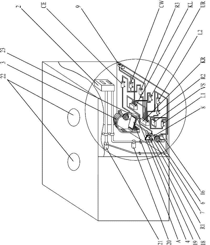
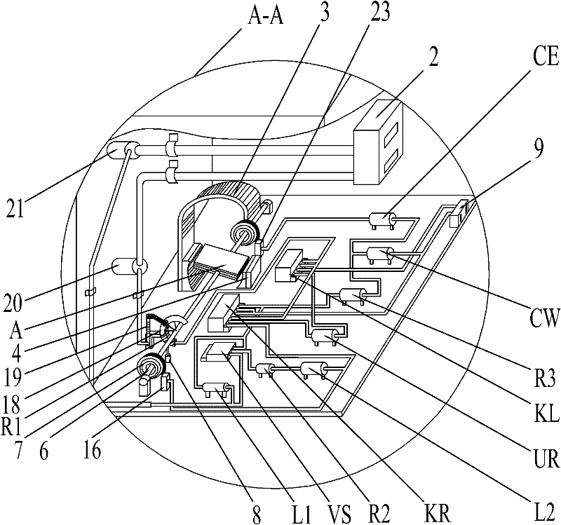
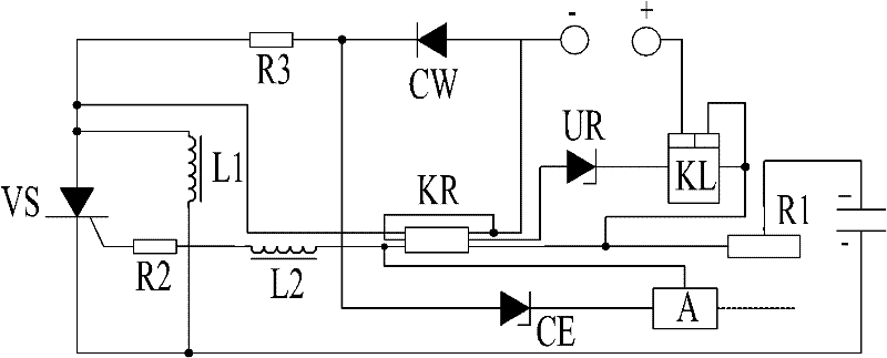
[0007] Specific implementation mode one: combine figure 1 , figure 2 , image 3 Describe this embodiment, this embodiment includes housing, multiple sets of capacitors 1, DC charging socket 2, DC power supply socket 9, positive terminal 20 and negative terminal 21; multiple sets of capacitors 1, positive terminal 20 and negative terminal 21 are all fixedly installed inside the shell; the multiple sets of capacitors 1 are connected in parallel, and the multiple sets of capacitors 1 are fixed side by side in the shell, and the positive plates of the multiple sets of capacitors 1 are connected to the positive terminal 20 at the same time. The negative plate of the capacitor 1 is connected to the negative terminal 21 at the same time, the positive connecting wire and the negative connecting wire of the DC charging socket 2 are respectively connected to the positive connecting post 20 and the negative connecting post 21; the positive connecting wire and the negative connecting wi...
specific Embodiment approach 2
[0016] Specific implementation mode two: combination Figure 4 , Figure 5 Describe this embodiment, the difference between this embodiment and the specific embodiment is that the multiple sets of capacitors 1 are installed side by side on the fixed bracket, and the fixed bracket consists of a lower frame 4-1, a movable upper frame 4-2, two The support spring 4-3, two telescopic support rods 4-4 and two electromagnets 4-5 are composed; the positive plate of each group of capacitors 1 is fixedly connected with the lower frame 4-1 of the fixed bracket, and each group of capacitors 1 The negative plate is fixedly connected with the movable upper frame 4-2 of the fixed bracket, and the two electromagnets 4-5 are fixedly installed on the upper surface of the lower frame 4-1 respectively, and the two electromagnets 4-5 are respectively located in the lower frame 4-1. 1; one end of the two telescopic support rods 4-4 is respectively fixed on the upper surface of an electromagnet 4-5...
specific Embodiment approach 3
[0017] Specific implementation mode three: combination figure 1 Describe this embodiment, the difference between this embodiment and specific embodiment 1 or 2 is that it also increases the air pressure safety valve 22, and the air pressure safety valve 22 is embedded on the casing (1). Other composition and connection methods are the same as those in Embodiment 4. The function of the air pressure safety valve 22 is to balance the internal and external air pressure of the capacitor battery when the internal short circuit of the capacitor 1 causes the air pressure to be too high, so as to prevent the internal pressure of the capacitor battery from being too high to cause an explosion.
[0018] Working process of the present invention:
[0019]The charging operation of the battery is realized by connecting the DC charging socket 2 with the external DC power supply; the external DC power supply can be disconnected after the battery is fully charged. When the battery supplies po...
PUM
 Abstract
Description
Claims
Application Information
 - R&D
- Intellectual Property
- Life Sciences
- Materials
- Tech Scout
- Unparalleled Data Quality
- Higher Quality Content
- 60% Fewer Hallucinations
Browse by: Latest US Patents, China's latest patents, Technical Efficacy Thesaurus, Application Domain, Technology Topic, Popular Technical Reports.
© 2025 PatSnap. All rights reserved.Legal|Privacy policy|Modern Slavery Act Transparency Statement|Sitemap|About US| Contact US: help@patsnap.com


