
Large-scale motor combined type rotation shaft and assembling method thereof

A large-scale motor and assembly method technology, applied in electromechanical devices, electric components, manufacturing of motor generators, etc., can solve the problems of affecting the electromagnetic air gap of the motor, affecting the balance of the rotor, complex manufacturing process, etc., to ensure the electrical performance of the motor and the rotor. Balance, reduce the influence of the electromagnetic air gap of the motor, and make the lifting process safe and convenient.

Active Publication Date: 2011-09-21
上海电气集团上海电机厂有限公司
View PDF3 Cites 8 Cited by
  • Summary
  • Abstract
  • Description
  • Claims
  • Application Information

AI Technical Summary

Problems solved by technology

[0002] Today, high-power, low-speed variable-frequency variable-speed steel rolling motors have been used in more and more engineering occasions. As a large-scale motor, it is difficult to manufacture and the manufacturing cost is high, especially the rotor of this type of motor. If the traditional laminated yoke or integral forged yoke (rotating shaft) is used, the weight of the rotating shaft alone will exceed 100 tons. Not only is forging difficult and costly, but also the rigidity and strength of the rotating shaft cannot be guaranteed; Therefore, this type of motor mostly adopts a three-section combined shaft (yoke), in which the intermediate shaft (yoke part) is hollow, but the connection and fixing requirements of the three-section shaft are very high. If it is connected by traditional welding, However, the requirements for welding process and equipment are quite high, resulting in complex manufacturing process and difficulty in cost reduction.
[0003] In the application number 200710038566.3, the patent "Three-section rotating shaft of large rough rolling motor and its assembly method" is disclosed. This patent adopts the method of connecting the three-section shaft through screw, nut and positioning pin. Although this technology can reduce manufacturing costs and It can guarantee the stiffness and strength of the rotating shaft, but there is such a hidden danger, that is, because the shaft assembly spigot is a clearance fit, if the combined shaft is seriously eccentric, it will affect the electromagnetic air gap of the motor, thereby affecting the electrical performance of the motor, and affecting the balance of the rotor , resulting in excessive mechanical vibration; in addition, the above-mentioned rotating shaft also has the hidden danger of nut loosening during the operation of the rotor. Therefore, it is necessary to improve the structure and assembly method of this type of rotating shaft

Method used


Image

  • Large-scale motor combined type rotation shaft and assembling method thereof
  • Large-scale motor combined type rotation shaft and assembling method thereof
  • Large-scale motor combined type rotation shaft and assembling method thereof

Examples


Embodiment Construction

[0036] Specific embodiments of the present invention will be described in detail below in conjunction with the accompanying drawings.

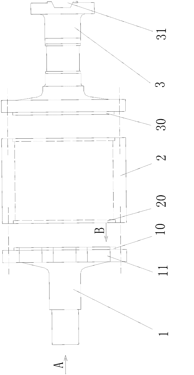
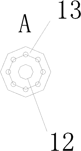
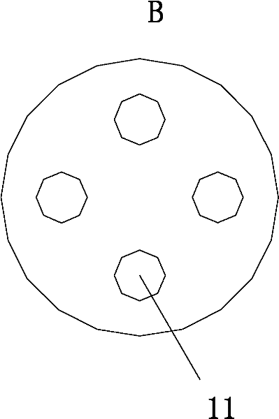
[0037] Please refer to Fig. 1 (a) to (c), a kind of large-scale motor combined shaft of the present invention comprises non-load end shaft 1 (ie small shaft), hollow shaft 2 and load end shaft 3 (ie flange shaft) connected in sequence ),in,

[0038] Both ends of the hollow shaft 2 are respectively provided with notches 20, and several screw holes (not shown in the figure) and several positioning pin holes (not shown in the figure) are evenly distributed along a circumference;

[0039] The end surface of the non-load end shaft 1 connected to the hollow shaft 2 is provided with a convex seam 10 matching the concave seam 20 of the hollow shaft 2, a screw hole and a positioning pin hole, and the end surface is located on the inner side of the convex seam 10 along a There are four through holes 11 with a diameter of 500mm evenly distributed on the...


PUM


Abstract

The invention relates to a large-scale motor combined type rotation shaft and an assembling method thereof. The rotation shaft comprises a non-load end shaft, a hollow shaft and a load end shaft which are connected in sequence, wherein the two ends of the hollow shaft are provided with concave seam allowances respectively and a plurality of screw holes and a plurality of positioning pin holes aredistributed along the circle of the hollow shaft; the end surface of the non-load end shaft and the end surface of the load end shaft which are connected to the hollow shaft are provided with convex seam allowances which are matched with the concave seam allowances, screw holes and positioning pin holes; and the non-load end shaft and load end shaft are assembled through the concave seam allowances and the convex seam allowances on the hollow shaft and are tightly and fixedly connected to the hollow shaft by a screw and a positioning pin in an axial fixing way. According to the large-scale motor combined type rotation shaft and the assembling method, the situation that a nut of a rotor loosens in the running process is prevented effectively and the working reliability of the rotor is improved greatly; meanwhile, the alignment and adjustment of the combined shaft centre are more accurate and the operation is more convenient, so that the electrical property of the motor and the rotor balance are guaranteed and the problem of superstandard mechanical vibration is solved.

Description

technical field [0001] The invention relates to a large motor combined rotating shaft and an assembly method thereof. Background technique [0002] Today, high-power, low-speed variable-frequency variable-speed steel rolling motors have been used in more and more engineering occasions. As a large-scale motor, it is difficult to manufacture and the manufacturing cost is high, especially the rotor of this type of motor. If the traditional laminated yoke or integral forged yoke (rotating shaft) is used, the weight of the rotating shaft alone will exceed 100 tons. Not only is forging difficult and costly, but also the rigidity and strength of the rotating shaft cannot be guaranteed; Therefore, this type of motor mostly adopts a three-section combined shaft (yoke), in which the intermediate shaft (yoke part) is hollow, but the connection and fixing requirements of the three-section shaft are very high. If it is connected by traditional welding, However, the requirements for weld...

Claims


Application Information

Patent Timeline
Patent Type & Authority Applications(China)
IPC IPC(8): H02K7/00H02K15/00
Inventor 王赋滕文江
Owner 上海电气集团上海电机厂有限公司
Learn More