Optical lens for light-emitting diodes (LEDs)

An optical lens and LED chip technology, applied in the field of lenses, can solve the problems of uneven LED light, limited illumination area, and reduced brightness, and achieve the effects of improving LED luminous efficiency, increasing illumination area, and improving brightness and uniformity.

Inactive Publication Date: 2011-09-28
特殊光电科技(中山)有限公司
View PDF5 Cites 3 Cited by
  • Summary
  • Abstract
  • Description
  • Claims
  • Application Information

AI Technical Summary

Problems solved by technology

However, due to the small power of a single LED and the uneven light emitted by the LED, it is necessary to combine several LEDs and perform secondary light distribution on the scattered light emitted by the optical lens to improve the light output efficiency of the LED and change the light distribution of the LED; At the same time, due to the small size of the LED, it needs to be installed on the substrate, so the irradiation area of ​​the traditional LED is greatly limited by the influence of the substrate, although the LED light source can be extended to increase the irradiation area of ​​the LED in the prior art. The lens, but this lens will also play a role in scattering light, so that the brightness in the effective area of ​​​​the LED light source is reduced, so there is a disadvantage of low luminous efficiency

Method used


Image

  • Optical lens for light-emitting diodes (LEDs)
  • Optical lens for light-emitting diodes (LEDs)
  • Optical lens for light-emitting diodes (LEDs)

Examples


Embodiment Construction

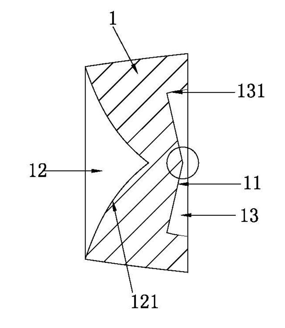
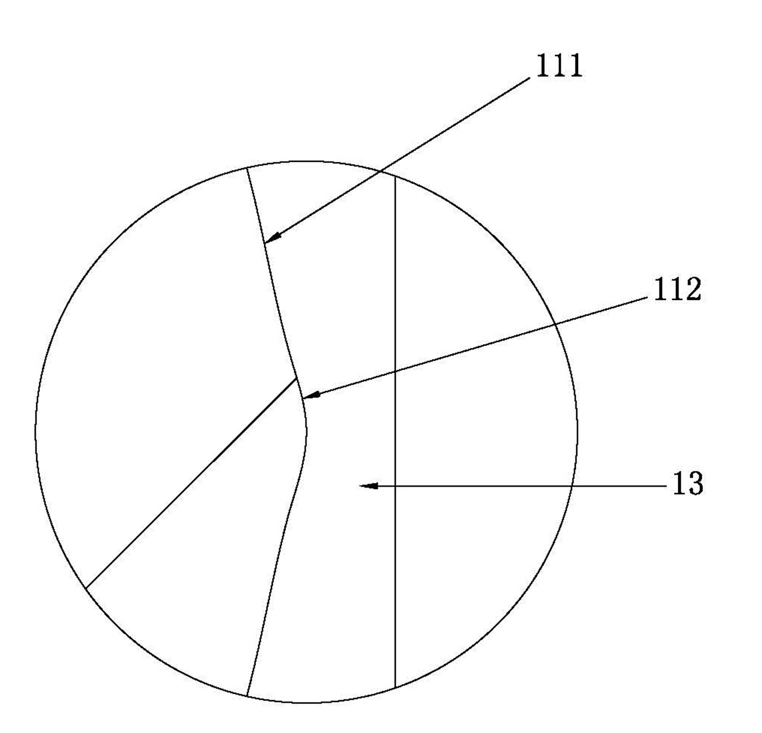
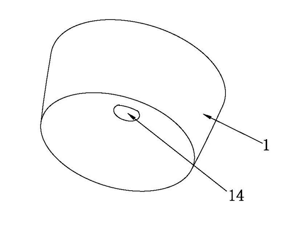
[0017] refer to figure 1 , figure 2 , figure 1 , figure 2 It is a structural schematic diagram of the first embodiment of the present invention. The optical lens for LED shown in the figure includes a cylindrical lens body 1. The cylindrical lens body 1 can be in the shape of a cone or a cylinder. The cylindrical lens The height of body 1 can be determined according to actual needs, certainly, cylindrical lens body also can be other polygonal cylinder shapes, and this lens body 1 has a convex incidence surface 11 and an inner space 12, and this inner space 12 has the structure that makes The light that enters from this incident surface reflects the internal reflection surface 121 of this lens body, and this internal space 12 can be conical shape, also can be other shapes, as can adopt the shape that generatrix is ​​incurved arc, polygonal pyramid etc. .

[0018] Such as figure 2 As shown, the convex incident surface 11 can be a closed curved surface formed by a straigh...


PUM


Abstract

The invention discloses an optical lens for light-emitting diodes (LEDs). The optical lens comprises a cylindrical lens body and is characterized in that: the lens body is provided with a raised incident surface and an internal space; and the internal space is provided with an internal reflecting surface which makes light rays from the incident surface reflected out of the lens body. By the optical lens, due to the light gathering effect of the raised incident surface, the light rays which are emitted from an LED light source is refracted by the raised incident surface to form parallel light beams, the light beams are projected to the internal reflecting surface of the internal space, and the light rays are reflected out through the internal reflecting surface, so that the illuminated area of the LED light source is improved and can reach 300 DEG, the luminance and the uniformity degree of the LED light source in an effective area are improved, and the luminous efficiency of the LEDs is improved.

Description

technical field [0001] The invention relates to a lens, in particular to a lens used for an LED light source. Background technique [0002] LED (Light Emitting Diode) has been widely used as a lighting source. Due to the special light-emitting principle of LED, the energy consumed by it to achieve the same brightness is far lower than that of ordinary incandescent lamps. With further breakthroughs in key technologies, the light efficiency of LED may be further improved, greatly surpassing all current lighting The light effect of the light source has an attractive prospect in lighting. However, due to the small power of a single LED and the uneven light emitted by the LED, it is necessary to combine several LEDs and perform secondary light distribution on the scattered light emitted by the optical lens to improve the light output efficiency of the LED and change the light distribution of the LED; At the same time, due to the small size of the LED, it needs to be installed o...

Claims


Application Information

Patent Timeline
Patent Type & Authority Applications(China)
IPC IPC(8): F21V5/04F21Y101/02F21Y115/10
Inventor 霍志民梁键珀
Owner 特殊光电科技(中山)有限公司
Why Eureka
Try Eureka