
Method, terminal and system for measuring asymmetric time delay of transmission link

A transmission link and asymmetrical technology, applied in the field of optical communication, can solve the problems of inconvenient project opening, no mature solution, and low accuracy of delay measurement, so as to save testing and avoid inconvenience

Inactive Publication Date: 2011-09-28
ZTE CORP
View PDF2 Cites 24 Cited by
  • Summary
  • Abstract
  • Description
  • Claims
  • Application Information

AI Technical Summary

Problems solved by technology

[0003] However, the existing 1588 protocol does not have a mature solution for how to calculate the asymmetric delay of the transmission link
However, in practical applications, when the equipment is turned on, the connection of the optical fiber is often exchanged manually, and the asymmetric delay of the line is measured through an external instrument. , which brought a lot of inconvenience to the opening of the project

Method used


Image

  • Method, terminal and system for measuring asymmetric time delay of transmission link
  • Method, terminal and system for measuring asymmetric time delay of transmission link
  • Method, terminal and system for measuring asymmetric time delay of transmission link

Examples


Embodiment Construction

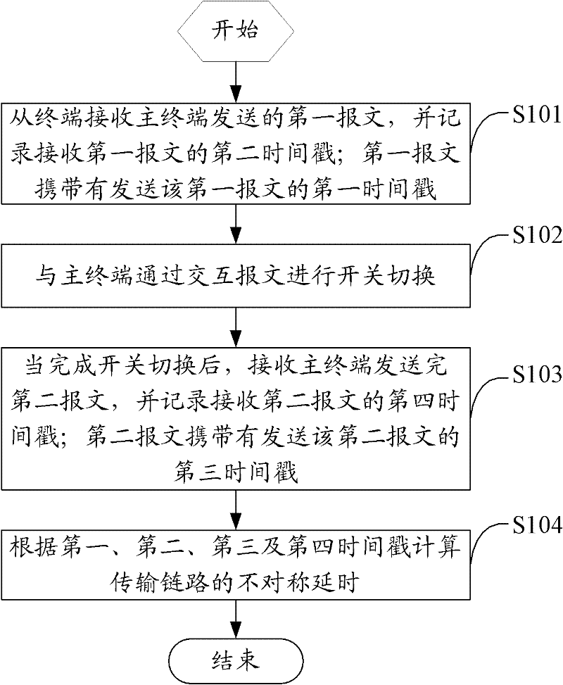
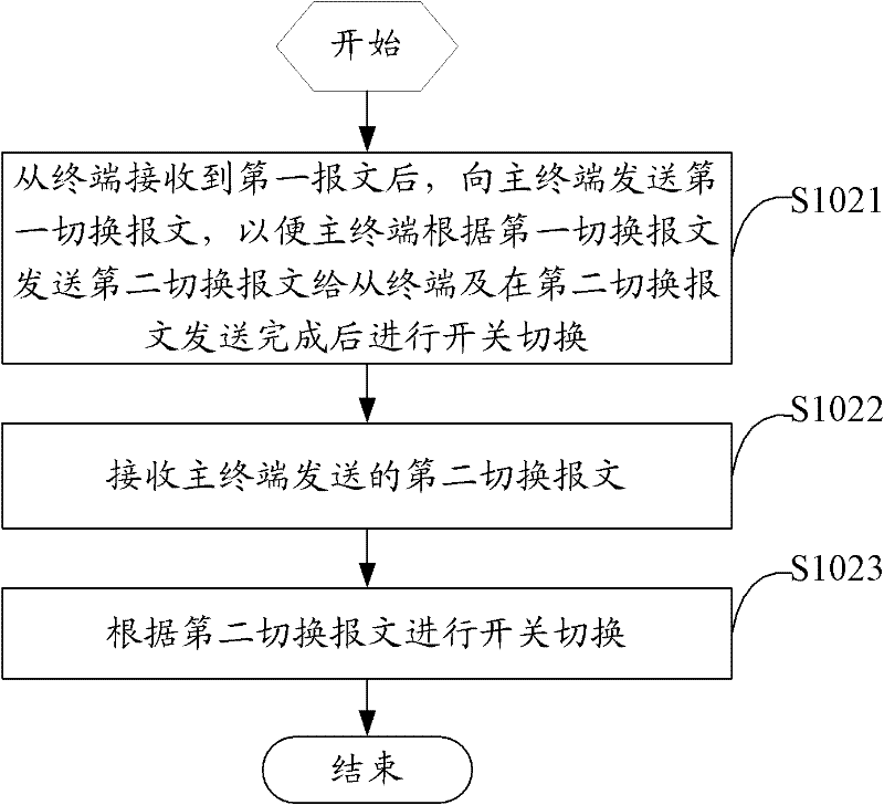
[0038] The solution of the embodiment of the present invention is mainly to realize the clock synchronization of the master and slave terminals at both ends of the transmission link by using the synchronous Ethernet function, and record the message transmission and reception at both ends of the master and slave terminals by recording the message receiving and sending timestamp. Timestamp, the optical fiber on the link is switched by a switch, and the message is sent again after switching and the timestamps of the message at both the master and slave terminals are recorded. The slave terminal is based on the four timestamps obtained twice, The asymmetric delay on the transmission link can be quickly calculated.

[0039] Such as figure 1 As shown, an embodiment of the present invention proposes a method for measuring asymmetric delay of a transmission link, including:

[0040] Step S101, receiving the first message sent by the master terminal from the terminal, and recording the seco...


PUM


Abstract

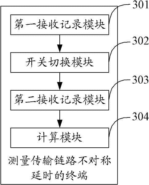
The invention relates to a method, terminal and system for measuring the asymmetric time delay of a transmission line. The method comprises the following steps: a slave terminal receives a first message carrying a first timestamp sent by a master terminal, and records a second timestamp receiving the first message; the slave terminal and the master terminal perform switch changeover through message interaction; after that, the slave terminal receives a second message carrying a third timestamp sent by the master terminal, and records a fourth timestamp receiving the second message; and the slave terminal calculates the asymmetric time delay of the transmission line according to the first, second, third and fourth timestamps. According to the invention, the clocks of the master and slave terminals are synchronized by synchronizing Ethernet, the timestamps of receiving and sending messages of the master and slave terminals are recorded, and the optical fiber on the link is changed over in a changeover switch mode; after the changeover, the message is sent again and the timestamps of the message at the master and slave terminals are recorded, and the slave terminal can quickly calculate the asymmetric time delay of the transmission link according to the obtained four timestamps, wherein the precision can reach the nanosecond level; and the measurement process is simplified.

Description

Technical field [0001] The present invention relates to the field of optical communication technology, in particular to a method, terminal and system for measuring asymmetric delay of a transmission link. Background technique [0002] At present, time transmission technology is more and more widely used in transmission networks. In order to achieve high-precision time transmission, the current transmission network is mainly based on the 1588 protocol to realize the time transmission between different sites. The 1588 protocol and synchronous Ethernet can be used. Realize time transfer at the nanosecond level. [0003] However, the existing 1588 protocol does not have a mature solution for how to calculate the asymmetric delay of the transmission link. In practical applications, when the equipment is turned on, the fiber connection is often switched manually, and the asymmetric delay of the line is measured through an external instrument. Not only the delay measurement accuracy is n...

Claims


Application Information

Patent Timeline
IPC IPC(8): H04L12/56H04J3/06H04L12/26
CPCH04J3/0667H04J3/0641H04J3/06H04L12/56H04L43/106H04L43/0858H04L43/50
Inventor 詹海亮张高安李晓霞
Owner ZTE CORP
Learn More