Method for cleaning a vacuum pump

A vacuum pump and cleaning technology, applied in the direction of using liquid cleaning methods, cleaning methods and utensils, cleaning hollow objects, etc., can solve the troublesome and time-consuming problems of cleaning vacuum pumps

Inactive Publication Date: 2011-09-28
OERLIKON LEYBOLD VACUUM +1
View PDF1 Cites 4 Cited by
  • Summary
  • Abstract
  • Description
  • Claims
  • Application Information

AI Technical Summary

Problems solved by technology

Cleaning vacuum pumps is cumbersome and time-consumin

Method used


Image

  • Method for cleaning a vacuum pump
  • Method for cleaning a vacuum pump
  • Method for cleaning a vacuum pump

Examples


Embodiment Construction

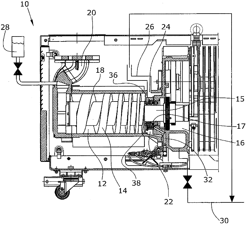
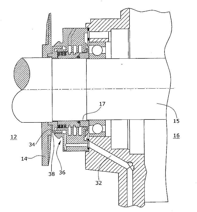
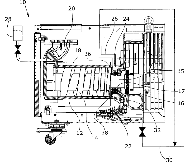
[0017] The illustrated vacuum pump 10 comprises a pump chamber 12 (suction chamber) in which a rotor 14 is supported for axial compression. The rotor 14 is driven via a transmission arranged outside the pump chamber 12 and contained in a transmission compartment 16 . The pump chamber 12 is enclosed by a housing 18 . Housing 18 has a pump chamber inlet 20 and a pump chamber outlet 22 . The shaft 15 of the rotor 14 enters the transmission compartment 16 from the pump chamber 12 through a passage 17 between the housing 18 and the transmission compartment 16 . exist figure 2 Channel 17 is shown in detail in .

[0018] A degassing opening 24 is formed in the top of the housing, and a degassing duct 26 is provided on the degassing opening 24 . The degassing pipe 26 is connected with the exhaust line 30 , and the exhaust line 30 is connected with the pump chamber outlet 22 .

[0019] When the vacuum pump is operated with water vapor and diethylzinc, these substances react as th...


PUM


Abstract

The invention relates to an effective method for cleaning a vacuum pump (10) comprising a pump chamber (12) with at least one pump rotor (14), characterized by the steps of: a) filling the pump chamber (12) with a cleaning fluid (28), b) distributing the cleaning fluid (28) in the pump chamber (12), c) dissolving impurities using the cleaning fluid (28) and d) draining the cleaning fluid (28) from the pump chamber (12).

Description

technical field [0001] The invention relates to a method for cleaning a vacuum pump comprising a pump chamber with at least one pump rotor. Background technique [0002] In various applications of such vacuum pumps, there is the problem that impurities are formed during operation and accumulate in the suction chamber (pump chamber). Applications here are, for example, MOCVD processes, LPCVD processes, PECvVD processes, PVD processes or the lamination of photovoltaic modules. These processes are processes using a process gas or forming reaction products in a process chamber, where the reaction products decompose in a vacuum pump or react with each other due to pressure / temperature conditions. As a result, particles are formed that grow in the layer or exist as dust. [0003] For example, one such application of vacuum pumps is the use of vacuum pumps to deposit transparent conductive oxide layers (TCO layers) for the fabrication of solar cells. For example, the TCO layer i...

Claims


Application Information

Patent Timeline
IPC IPC(8): B08B3/08B08B9/00F04C29/00
CPCF04C2220/10B08B3/08F04C2280/02B08B9/00F04C18/16F04C29/00
Inventor 英戈·坎嫩哈根·格特利希斯特凡·施奈德
Owner OERLIKON LEYBOLD VACUUM
Why Eureka
Try Eureka