Inductance coil for electric power grids having reduced sound emission

A choke coil and coil technology, applied in the direction of transformer/inductor coil/winding/connection, transformer/inductor components, transformer/inductor noise damping, etc. Danger of voltage arcing, low sound emissions, effect of less noise

Active Publication Date: 2011-09-28
COIL HLDG
View PDF2 Cites 2 Cited by
  • Summary
  • Abstract
  • Description
  • Claims
  • Application Information

AI Technical Summary

Problems solved by technology

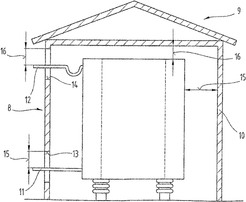
For example, the openings 13, 14 in the soundproof housing 8 for the passage of electrical connections must have the necessary or at least necessary safety distances 15, 16, which leads to a considerable deterioration of the effectiveness of the sound shielding effect

Method used


Image

  • Inductance coil for electric power grids having reduced sound emission
  • Inductance coil for electric power grids having reduced sound emission
  • Inductance coil for electric power grids having reduced sound emission

Examples


Embodiment Construction

[0047] At the outset, it should be pointed out that in the differently described embodiments the same parts are provided with the same reference symbols or the same component designations, wherein the disclosure contained in the entire description can be transferred according to the meaning to those with the same reference symbols or On the same part with the same component name. The positional specifications selected in the description, such as top, bottom, side, etc., also refer to the directly described and illustrated figures, and in the event of a change in position, these positional specifications are automatically transferred to the new position. Furthermore, individual features or combinations of features from the various exemplary embodiments shown and described can form independent, inventive or inventive solutions.

[0048] All descriptions of numerical ranges in the specific description should be understood as they include any and all of the partial ranges, for exa...


PUM


Abstract

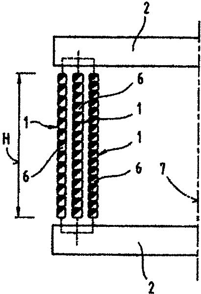
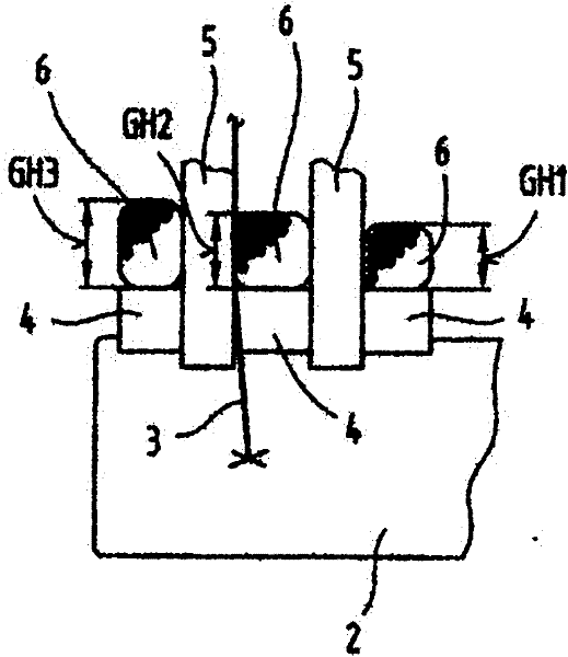
The invention relates to an inductance coil, particularly an inductance coil without iron core for use in electric power grids, comprising at least two cylindrical winding layers (1), which are disposed concentrically with respect to a coil center line (7) and are connected electrically in parallel. The inductance coil comprises at least one means for reducing or minimizing sound emissions developing during operation of the inductance coil. At least the outermost winding layer (1) is designed as a current-conducting, acoustic shield winding (18) with respect to the winding layer (1) adjoining in the direction of the center line (7), wherein the shield winding (18) is dimensioned electrically such that it is designed for the transmission of a current intensity which is between the 0.1% to the maximum 50% of the current intensity transmitted by the adjacent winding layer (1) towards to the direction of the coil center line (7). The invention further relates to a clamp-like retaining element disposed on at least one face end of the inductance coil for reducing sound emissions.

Description

technical field [0001] The invention relates to a choke coil / induction coil, in particular a choke coil without an iron core, for use in a power supply network, comprising at least two cylindrical winding layers arranged concentrically with respect to the central axis of the coil and electrically connected in parallel , and comprising at least one means for reducing or minimizing the sound emissions generated during operation of the choke coil, as given in claim 1 or 18. Background technique [0002] In the case of a coil, in particular a dry-insulated choke coil without an iron core, which comprises two or more cylindrical winding layers arranged concentrically with each other with a gap and electrically connected in parallel, It is known to wind winding layers from rectangularly shaped conductors or conductor bundles, wherein the winding layers have a different number of turns, mainly decreasing from the inside to the outside. The principle configuration of concentrically...

Claims


Application Information

Patent Timeline
Patent Type & Authority Applications(China)
IPC IPC(8): H01F27/30H01F27/33H01F37/00
CPCH01F27/303Y02E60/321H01F27/33H01F37/005
Inventor A·格里森蒂J·埃德J·米莱德
Owner COIL HLDG
Why Eureka
Try Eureka